|
|
 Posted - December 04 2015 : 8:01:47 PM Posted - December 04 2015 : 8:01:47 PM


|
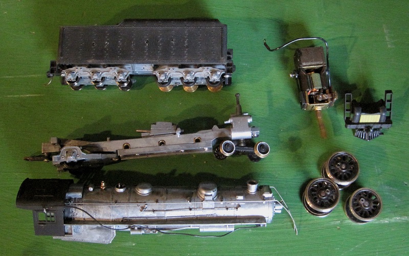
I picked up a used Mantua Pacific with Power Drive (the bigger motor and separately mounted worm). It had a flaking scabby looking paint job, so I disassembled it and stripped the paint so it was basically back to kit form:
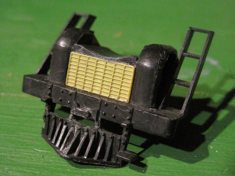
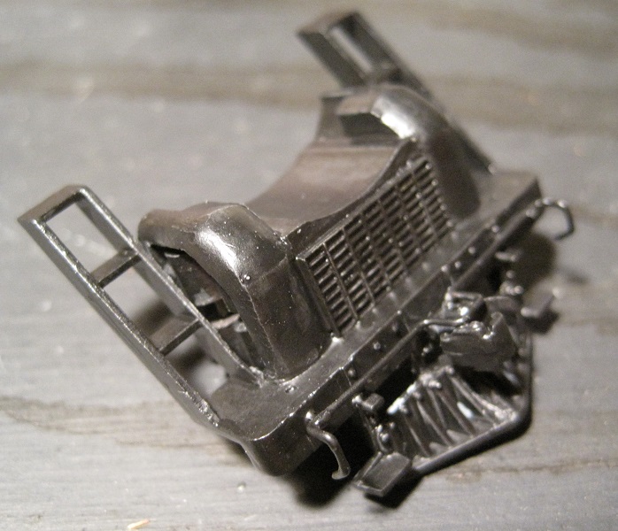
I like to add a little extra detail to the pilot. Here you can see a pilot that I customized for another engine on the left, and the pilot from my new engine on the right. You can see that the compressor housings have a blank surface where you'd usually see a cross-compound compressor. There's another blank surface where many railroads had a grill for the air cooler (when you compress air it gets really hot). There's no front coupler. The right step is broken off and there's no uncoupling lever.
Here's a front view of the previous pilot showing a dummy coupler and uncoupling levers and the cooling grill (made of a piece of roof walk cut to size and filed thinner).
This view shows the compressor inside the housing of the previous engine's pilot:
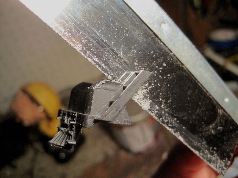
I used a razor saw to cut off the blank wall and expose the hollow housing:
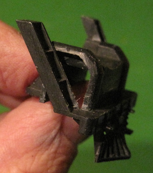
Here the blank wall is removed and the edge is filed into a nice curved edge:
The grill has been added. A roof walk from a scrapped covered hopper was cut to shape, filed thinner and glued on:
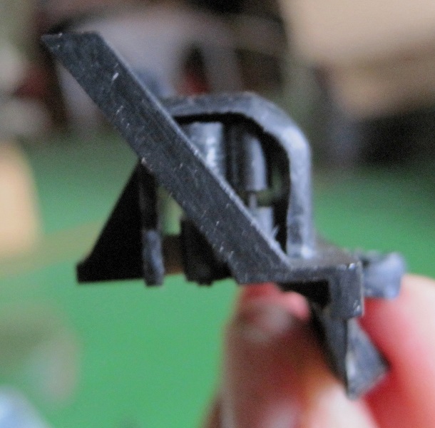
In the lower left of this picture is a Model Die Casting cross-compound compressor. Previously, I cut and filed these to fit the hole, but you really can't see them very well and, now that you can't get these so easily any more, I considered it more light than I wanted to hide under a basket. The crude models above it are meant to suggest a compressor and I can make all that I want of them from my supply of sprues and wire. You can see the hole in which one will be placed:
Here's an installed compressor. To me, anyway, it's close enough for government work. In normal lighting, you only perceive it as a shape in the shadows.
The compressor is glued to the inside of the housing on top, and to a scrap plastic brace on the bottom:
Here's the finished pilot, paint and all:
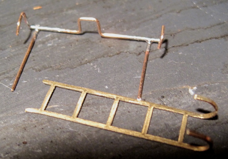
The next stage in the project is the tender. It already had a Kadee coupler, but I wanted to add an uncoupling lever and replace the cast on ladder with a separately applied one. Here are the ladder and the uncoupling lever. The ladder is just brass ladder stock. The lever is bent from .020" bronze wire. Its stanchions are just more wire soldered on:
The ladder and uncoupling lever are installed. Also, the blank face of the backup light lens has been drilled out and replaced with a cylinder of clear plastic sprue turned to size with a file and a drill.
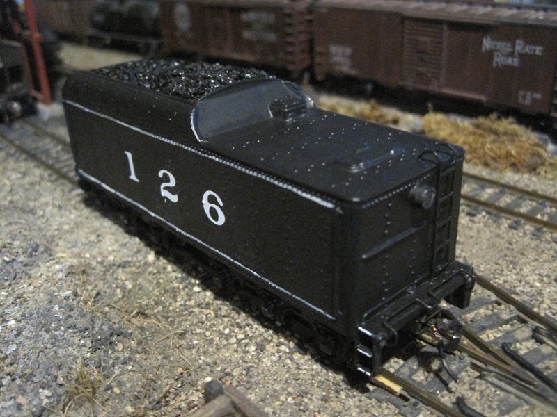
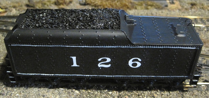
The tender is sporting new paint and a road number. Real coal has been glued over the plastic coal with Duco Cement. Additional layers are glued to that first coat with diluted carpenter's glue.
More to come.
Carpe Manana!
|
Country:  USA ~
Posts: 2417 ~
Member Since: September 17 2013 ~
Last Visit: June 14 2026 USA ~
Posts: 2417 ~
Member Since: September 17 2013 ~
Last Visit: June 14 2026
|
 Alert Moderator
|
|
|
|
Posted - December 04 2015 : 8:19:17 PM
|
| Welcome back after the "break" Don. One of the things I like about your posts is that I usually learn something about some functional part of a locomotive and that helps me understand why and where a certain detail is added. Looks to me like you handle a soldering iron pretty well.
|
|
Country: USA ~
Posts: 2087 ~
Member Since: March 16 2013 ~
Last Visit: July 05 2018
|
Alert Moderator

|
|
|
|
Posted - December 05 2015 : 5:56:34 PM
|
quote:Welcome back after the "break" Don. One of the things I like about your posts is that I usually learn something about some functional part of a locomotive and that helps me understand why and where a certain detail is added. Looks to me like you handle a soldering iron pretty well.
Originally posted by Barry - December 04 2015 : 8:19:17 PM
|
Thanks. For the soldering, the thing I learned that helped me most was to tin both parts with solder separately and then put the pieces together and heat the joint so the solder joint melts together. I used to royally mess it up when I tried to heat the two parts and add in the solder so I needed 3 hands.
Carpe Manana!
|
|
Country: USA ~
Posts: 2417 ~
Member Since: September 17 2013 ~
Last Visit: June 14 2026
|
Alert Moderator
|
|
|
|
Posted - December 06 2015 : 11:49:53 PM
|
Today, I did a little tinkering on the boiler and cab. I think these locomotives look better with a cab support sheet. I also like to add the deck plate between the cab and tender:
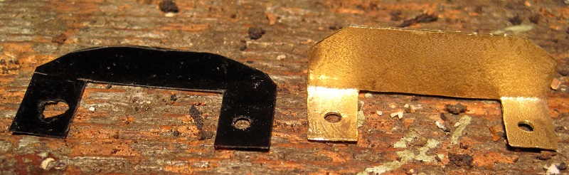
The brass piece is the cab support sheet. I split open and flattened a shell casing from some sort of rifle bullet. I couldn't tell you what kind. I just found the thing on the ground somewhere out in the woods. Then, I sawed out the shape with a jeweler's saw and bent the mounting flanges 90 degrees to the sheet and drilled out the screw holes. The black piece is the deck plate. It's made of photographic film from the end of the roll before the pictures start. I'm no longer shooting film, but when I did I saved these scraps. The film is flexible enough to yield when the cab moves up and down compared to the tender.
Here are the parts mounted:
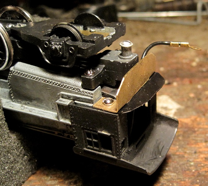
I drilled and tapped holes for 2-56 mounting screws in the boiler casting.
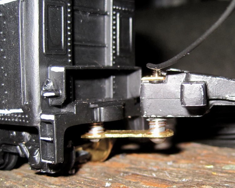
I like to be able to take the boiler off of a locomotive without fighting with the headlight wire, so there will be a little spring contact on the frame that touches this brass contact plate on the underside of the boiler:
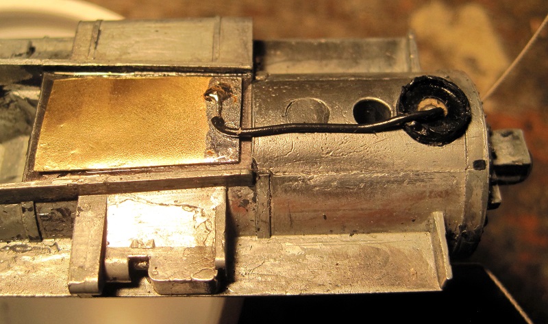
This is a piece of brass (also from a bullet cartridge) that is epoxied to a thin piece of plastic which is, in turn, epoxied to the underside of the boiler casting. The headlight wire is soldered to it.
I also epoxied little pieces of brass to the sand dome to represent filler hatches:
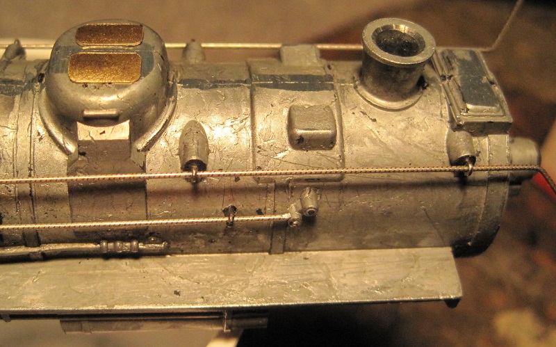
I also beveled the smokestack opening a little to make the stack look a little less out of scale thick and filed down the mold parting lines on the boiler casting.
More to come.
Carpe Manana!
|
|
Country: USA ~
Posts: 2417 ~
Member Since: September 17 2013 ~
Last Visit: June 14 2026
|
Alert Moderator
|
|
|
|
Posted - December 11 2015 : 6:15:01 PM
|
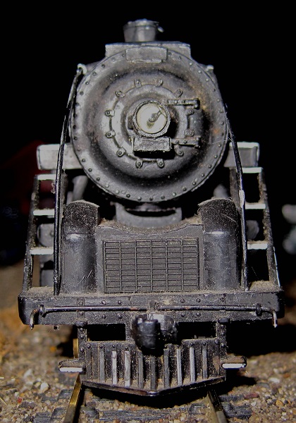
The basic cosmetic changes to the boiler, cab and pilot are now complete. Here's a front view of the engine:
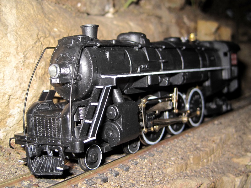
White trim has been added to the steps and walkways. The road number has been added to the headlight.
Here's a rear view:
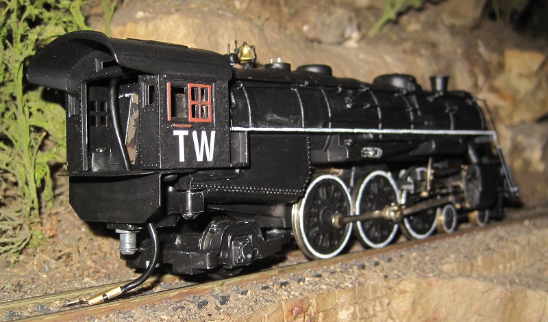
You can see the cab support sheet, the bridge plate for the tender and the reporting marks on the cab.
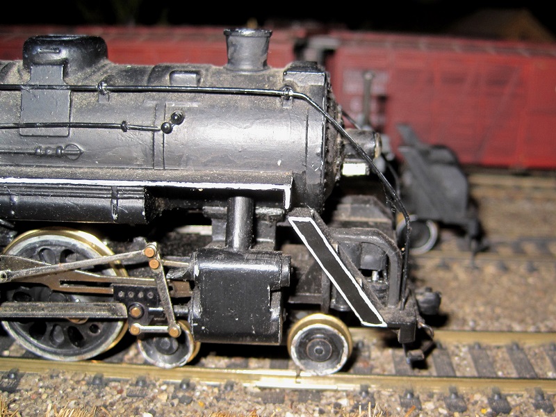
The side view shows the general paint job, the bell with a bracket and the exhaust pipe added to the dynamo. That's a small detail, but to me, it's a conspicuous one:
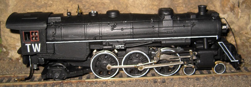
Still to come: electrical changes to the frame and drawbar.
Carpe Manana!
|
|
Country: USA ~
Posts: 2417 ~
Member Since: September 17 2013 ~
Last Visit: June 14 2026
|
Alert Moderator
|
|
|
|
Posted - December 11 2015 : 9:21:23 PM
|
| Nice engineering Don. I dig the cab support plate. That area of the locomotive between the locomotive and the tender always strikes me as an ominous pit that engineers and fireman can fall into. Man, you hammered out that shell nice and flat. I pick up stuff like that I see on the ground as well. What does TW on the cab stand for?
|
|
Country: USA ~
Posts: 2087 ~
Member Since: March 16 2013 ~
Last Visit: July 05 2018
|
Alert Moderator
|
|
|
|
Posted - December 11 2015 : 9:26:20 PM
|
That is some nice close up photography. What are you using for a camera? It's like, I'm noting the "ribbon" (or whatever manufacturing mark that may be) running along the handrail wire. quote:
|
|
Country: USA ~
Posts: 2087 ~
Member Since: March 16 2013 ~
Last Visit: July 05 2018
|
Alert Moderator
|
|
|
|
Posted - December 11 2015 : 10:44:02 PM
|
The TW is Tabor and Waldo. It's a kind of tongue in cheek rebellion against the well-defined layout period and location that has gained popularity lately.
In the Bible, Moses and Elijah appear transfigured with Jesus on Mt. Tabor. Given the years between the lives of these three individuals, I call that the greatest anachronism in history. So much for a well defined "period" for my layout. 
As for Waldo, the location is equally poorly defined. There is a whole series of books in print wondering where Waldo is. 
The camera is a little Canon digital pocket camera. It shoots at 10 megapixels, but I crop and resize down to 800 x 600 pixels. This means that I can just back off a bit if I need more depth of field, and then crop down to the image I want.
I do sometimes fire on an engine that has no bridge plate between the engine and tender and it does help to pay attention. The bridge plate requires a little attention, too. It's fastened better to the engine than the tender and slides around on the tender deck. You want to watch where your feet are so you don't get one pinched by that moving plate.
Carpe Manana!
|
|
Country: USA ~
Posts: 2417 ~
Member Since: September 17 2013 ~
Last Visit: June 14 2026
|
Alert Moderator
|
|
|
|
Posted - December 14 2015 : 10:49:00 PM
|
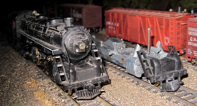
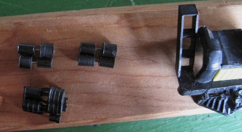
Today, I did electrical modifications. Out of the box, the engine picks up from the right rail on the three right drivers and from the left on 4 of the tender wheels. I had already added metal wheels on the right side of the pilot truck to add pickup from the right rail, there. I had also changed the tender trucks so all 6 axles pick up power from the left rail. Today's modification was to pick up power from the two flanged drivers on the left side. I also modified the engine to get the power from the tender through the drawbar rather than through that big old wire.
Here's a general overview of the modified frame:
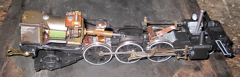
From left to right, you can see:
1) The metal drawbar and a wire running forward from its mounting setup
2) A mounting bracket for the pickup wiper to the left rear driver (the wire from the drawbar is connected to that). The mounted bracket is soldered to a piece of printed circuit board that is epoxied to the frame.
3) A raised terminal with a screw to hook up a wire to the motor and a wire to the front pickup and the contact to the headlight. This is also mounted on a piece of PC board.
4) A mounting bracket for the pickup wiper to the left front driver and for the contact to the headlight. Pickup wipers are made of phosphor bronze and the mounting brackets are brass.
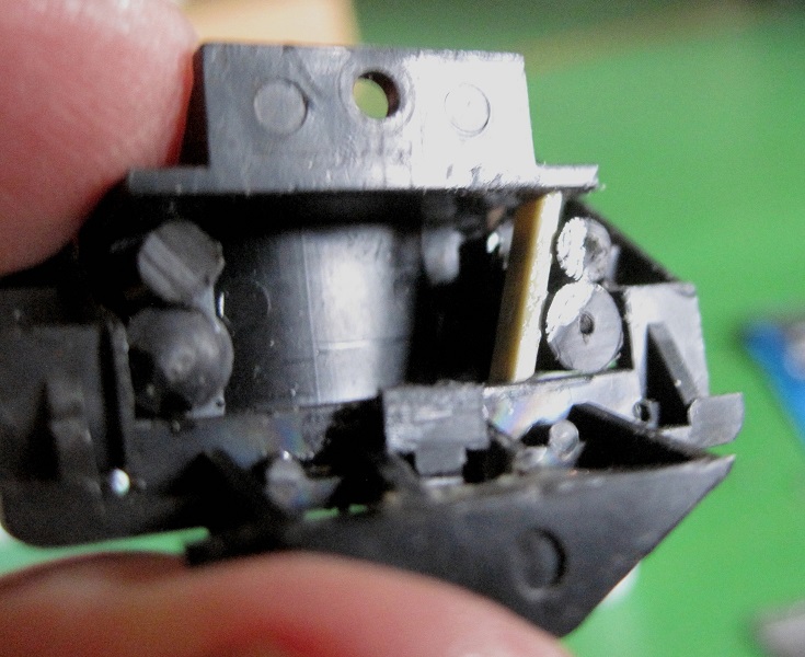
Here's some more detail regarding the powered drawbar mounting:
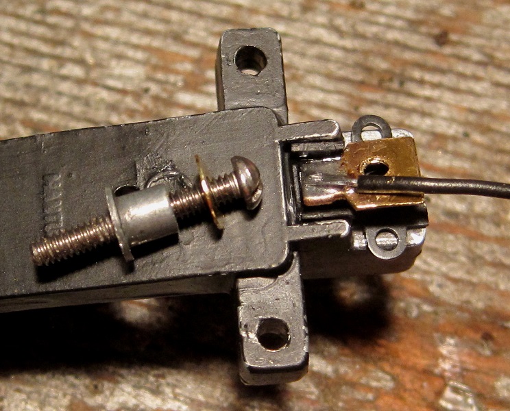
I cut the post to which the drawbar is mounted from the frame with a jeweler's saw and made a washer out of brass. I drilled out the screw hole to the outside diameter of the coupler pivot post in a Kadee coupler box. From the tops of two coupler boxes, I made insulated collars that guide a 2-56 screw through the frame without touching it. I tapped a thick piece of brass and soldered a wire to it. The screw comes up from the bottom through the washer, the drawbar pivot post, the bottom insulated collar, the top insulated collar and the tapped brass piece.
Here, you can see the whole thing assembled:
The coil springs on top of the drawbar hold it tightly in position so it doesn't rattle, breaking contact with the engine and tender. The springs are wound from .015" phosphor bronze wire, since I couldn't find springs of the size and tension I wanted.
This view of the left side of the engine provides a better view of the pickup wipers and the wire to the motor:
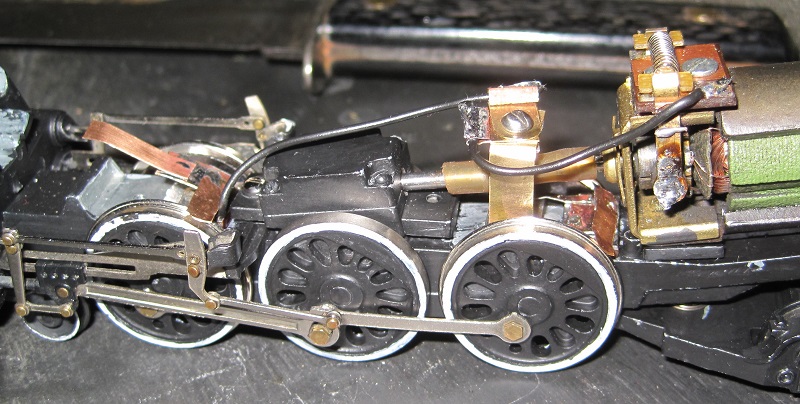
Presently, there is primer paint drying on all that clutter. It'll be painted black and hidden in the shadows under the boiler.
Carpe Manana!
Edited by - scsshaggy on December 14 2015 10:52:30 PM
|
|
Country: USA ~
Posts: 2417 ~
Member Since: September 17 2013 ~
Last Visit: June 14 2026
|
Alert Moderator
|
|
|
|
Posted - December 15 2015 : 4:28:01 PM
|
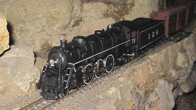
Here's the end result. I'll probably go back and weather it, later, but that'll be after I run it a while.

Carpe Manana!
|
|
Country: USA ~
Posts: 2417 ~
Member Since: September 17 2013 ~
Last Visit: June 14 2026
|
Alert Moderator
|
|
|
|
Posted - December 16 2015 : 6:54:54 PM
|
That looks pretty fine Don. I believe I actually understand your wiring scheme.
Now, I wouldn't mind seeing a video of this "souped-up" locomotive running.
"From the tops of two coupler boxes, I made insulated collars . . . "; this is a great tip.
|
|
Country: USA ~
Posts: 2087 ~
Member Since: March 16 2013 ~
Last Visit: July 05 2018
|
Alert Moderator
|
|
|
|
Posted - December 17 2015 : 11:12:47 AM
|
This is all great stuff.
I'd like to appropriate some of these ideas, if you don't mind.
I've got three Mantua Pacifics that could use some of this attention.
Evan
|
Country:  Canada ~
Posts: 505 ~
Member Since: August 09 2014 ~
Last Visit: June 01 2026 Canada ~
Posts: 505 ~
Member Since: August 09 2014 ~
Last Visit: June 01 2026
|
Alert Moderator
|
|
|
|
Posted - December 18 2015 : 12:07:24 AM
|
quote:Now, I wouldn't mind seeing a video of this "souped-up" locomotive running.
Originally posted by Barry - December 16 2015 : 6:54:54 PM
|
Carpe Manana!
|
|
Country: USA ~
Posts: 2417 ~
Member Since: September 17 2013 ~
Last Visit: June 14 2026
|
Alert Moderator
|
|
|
|
Posted - December 18 2015 : 11:10:48 AM
|
| Looks to be a nice smooth running locomotive Don. Fun looking at your railway. Lots of interesting things to see and some great rock work and bridging. I liked seeing the train come from under the bridge and then wind along the ridge. Thanks man.
|
|
Country: USA ~
Posts: 2087 ~
Member Since: March 16 2013 ~
Last Visit: July 05 2018
|
Alert Moderator
|
|
|
|
Posted - December 18 2015 : 1:19:14 PM
|
|
As always excellent video of your equipment and layout. Thank you for sharing.
|
|
Country: USA ~
Posts: 7739 ~
Member Since: February 12 2014 ~
Last Visit: June 14 2026
|
Alert Moderator
|
|