|
|
 Posted - November 30 2014 : 1:53:52 PM Posted - November 30 2014 : 1:53:52 PM


|
I just received my order of springy phosphor bronze wire:
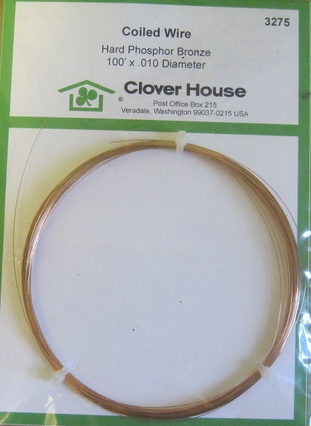
I was interested in making spring wire electrical pickups rather than flat phosphor bronze ones in some cases and wanted some .020" diameter wire for that, and for making railings. (Railing stanchions are drilled for .020" wire.) It needed to be hard phosphor bronze because regular brass wire is not springy enough and steel wire is hard to solder.
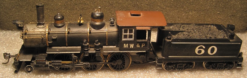
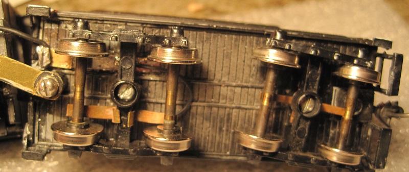
While ordering, I noticed that they had .010" wire, as well. I figured this size would be good for making custom coil springs for some applications. For example, I have an MDC Mogul that I modified, some years back, to pick up power through all the drivers and from both sides of the tender:
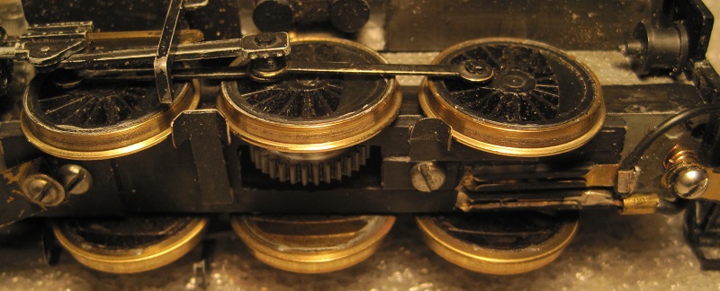
The drivers on the right side transmit power to the frame through the axles and bearings. Pickups were added to take power from the left rail:
The tender was changed so the frame is also grounded to the right rail, then one truck was changed to send power from the left rail through a wire to an electrically isolated strip of brass, which is in turn, wired to the left-side pickups on the engine:
The tender frame and locomotive frame are electrically connected through the drawbar. Since a loose drawbar screwed to the two frames is not a reliable connection, I originally put flat phosphor bronze pickups on the drawbar touching the posts to which the drawbar is screwed. These pickups turned out to be fragile and always damaged.
It occurred to me that a coil spring at either end of the drawbar would help it make a firm connection while still allowing some vertical flexibility between engine and tender. Finding springs of the right size and tension was nearly hopeless, but with the .010" spring wire, I made a couple of coil springs by wrapping the wire around the threads of a bolt. Here's the drawbar with its springs:
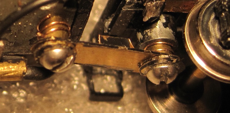
I've tested this some and it seems to work pretty well. It also tolerates more abuse than the previous arrangement. Note the little tails of wire sticking out past the edge of the drawbar. These were necessary to keep the spring from being pinched between the post and the drawbar.
Carpe Manana!
Edited by - scsshaggy on November 30 2014 1:57:43 PM
|
Country:  USA ~
Posts: 2416 ~
Member Since: September 17 2013 ~
Last Visit: February 09 2026 USA ~
Posts: 2416 ~
Member Since: September 17 2013 ~
Last Visit: February 09 2026
|
 Alert Moderator
|
|
|
|
Posted - November 30 2014 : 2:12:51 PM
|
Hey Don, This is a great close-up you posted; so clear. What did you use to take the picture (off topic, I know)? Pretty cool with the spring wire. I've been thinking of ordering some "flat" wire, like George used to do the bands on his General . . . so I could do some old Mantua tank cars that came missing the tank hold down straps (still off topic, geez).
Anyway, I'm diggin' your photo post and the good quality photos of the work and the explanations, but I guess I am totally ignorant about a basic fact that would allow me to understand this better . . .
You say you're getting all the drivers (right and left side) and both sides of the tender . . . so where is the "ground" in this system? It is my understanding that you are only getting power from one of the rails of the track . . . unless there is some divine intervention that I am not yet privy to? I'm probably/obviously misreading something, but I need to be straightened out on this whole concept of getting power from all the wheels.
Also . . . that is a bunch of work to go to . . . and as you say, potentially fragile connections . . . as such, do you feel that the performance gained is readily apparent, or is it yet another subtle thing and they all add up? Will this MDC mogul cruise really nice and slow and steady now and start out at an incredibly slow crawl? Not being a smart alec (?spelling?) . . . just darned interested in understanding this.
Thanks Don.

|
|
Country: USA ~
Posts: 2087 ~
Member Since: March 16 2013 ~
Last Visit: July 05 2018
|
Alert Moderator

|
|
|
|
Posted - November 30 2014 : 2:58:38 PM
|
Barry,
First, the easy question, I used a Canon PowerShot SD1200 IS Digital Elph to shoot the pictures. It's a pocket camera, but it has a pretty decent macro mode. The smaller a thing you try to shoot, the smaller will be the field of focus, so I usually shoot a larger area and crop to the view I want. At that, there are usually enough pixels left that I have to resize the picture smaller to make it upload and download gracefully, so nothing is lost in cropping.
I made some tank straps, once using some paper-thin copper sheet metal and cutting it to the desired width. Since tank straps usually terminate in a threaded rod, I soldered the ends to a wire and attached that to the car frame. I can't show pictures of that because I no longer have that car. The flat wire you found is still a bit thick, the thinnest being something like 7/8" thick in HO. I think it would be less of a fight to get something thinner bent into shape.
Now, back on topic, I'll answer the bigger question first. Is it worth it? My experience on my layout is that if you improve the electrical pickup a little, you improve the performance a lot. Whenever the engine loses contact with the rail, there's an arc which pits the metal a little and burns some dirt onto the wheel like burnt food crusted to the side of a pan. This causes poorer contact and more arcing in a cascading effect. Having more points of contact greatly delays this death spiral.
When I used to run a Mantua Prairie with just three drivers and 4 tender wheels for pickup on moderately, but not perfectly clean track, the wheels would be dirty and performance would be degraded in about ten minutes of normal operation. Normal operation includes some mainline running and some switching, in this case. Changing that same engine to pick up on all 6 drivers and two tender wheels on each rail allowed for a couple of hours before the engine gets finicky.
That's what prompted me to do the same for the Mogul shown above.
So how's it work? When I used the word grounded, it may have been a misuse of the word. I just meant that the engine and tender frames are both electrically connected to the right rail. On the engine, that's just the normal pickup through the driver axles. On the tender, the rear truck has the original MDC contacts that take power from the axles to the frame.
The front tender truck has axle wipers isolated from the frame sending power via various wires and parts to the locomotive's axle cover. The axle cover is a piece of printed circuit board with the plastic side against the frame and the copper side down. Pickup wipers to the left drivers are soldered to the PC board axle cover. A wire runs from that PC board to the motor brush that is isolated from the frame.
All this is way more complex and less foolproof than the original design, but I'm gradually arriving at a more bulletproof way of doing it (such as the coil springs replacing the fragile contacts).
Carpe Manana!
|
|
Country: USA ~
Posts: 2416 ~
Member Since: September 17 2013 ~
Last Visit: February 09 2026
|
Alert Moderator
|
|
|
|
Posted - December 01 2014 : 9:09:19 PM
|
Well gaining almost two hours in decent run time is significant, when you're comparing it to 10 minutes. And, I'm definitely aware of that crud buildup that you describe, though I do seem to be able to run my locomotives for a good while (maybe the neodymium magnets help "suck up" the electricity by helping the motor "draw" current? So . . . check me out on this and see if I have a correct understanding . . .
"The front tender truck has axle wipers isolated from the [tender; my word insertion here] frame sending power via various wires and parts to the locomotive . . . "
Hopefully I'm not interpreting your statement out of context here. What I get out of this is that (in addition to power being supplied to the locomotive/motor by the tender, as usual, though in this case by the rear tender wheels only) you are introducing a second source/route of power to the locomotive/motor via the front tender wheels, which have been isolated from the tender frame.
What I'm understanding then is that you still have the tender wheels (both front and back, though power through the front tender wheels goes directly to the locomotive/motor and the rear tender wheels power goes through the tender frame first) as the primary power source?
Do you have brass track?
|
|
Country: USA ~
Posts: 2087 ~
Member Since: March 16 2013 ~
Last Visit: July 05 2018
|
Alert Moderator
|
|
|
|
Posted - December 01 2014 : 10:05:19 PM
|
Stated more simply, all 6 drivers pick up power. The tender picks up from both rails, as well, the front truck from the left side and the rear truck from the right.
That means 5 wheels pick up from each rail. Before the engine can lose contact and pull an arc, all 5 pickup wheels on one side must lose contact.
What is nonstandard here is that the tender frame and locomotive frame are the same polarity as each other and as the right rail. The front tender truck and left drivers are both isolated from their respective frames and are the same as the left rail.
I have some brass and some nickel silver track. I know that's trouble, but it's easier to make the engines tolerant than to tear out and replace all the track at this stage of the game.
Carpe Manana!
Edited by - scsshaggy on December 01 2014 10:14:16 PM
|
|
Country: USA ~
Posts: 2416 ~
Member Since: September 17 2013 ~
Last Visit: February 09 2026
|
Alert Moderator
|
|
|
|
Posted - December 02 2014 : 10:23:12 AM
|
| What really "throws me" Don, is when you say that all the wheels pick up power from both rails. Isn't one of the rails "negative"?
|
|
Country: USA ~
Posts: 2087 ~
Member Since: March 16 2013 ~
Last Visit: July 05 2018
|
Alert Moderator
|
|
|
|
Posted - December 02 2014 : 11:28:00 AM
|
quote:What really "throws me" Don, is when you say that all the wheels pick up power from both rails. Isn't one of the rails "negative"?
Originally posted by Barry - December 02 2014 : 10:23:12 AM
|
B:
The pickups are riding on the insulated drivers, and they must be insulated from the frame as well, though I'm not sure how power gets from the forward pickup. The rear one shows some ingenious use of railjoiners. I'd certainly like to know more.
Your Nd magnets might be helping indirectly by reducing current draw, cutting down voltage drop due to contact resistance? But there are many variables in play with track dirt. Amount of dust, dust stickiness, and air moisture come into play. Track and wheel material type and hardness, mechanism lubricant type and practices, track-cleaning practices, power methods and equipment weight do too. Then there are allowances for table-thumping skill and cussword proficiency. It becomes one of those elaborate probabilistic multivariable messes like the Drake equation for interplanetary life, and like the Drake equation, the maintenance of track contact becomes a happy playground for all manner of unverifiable [crackpot] theories. Reading back issues of MR and MC, this appears to be something going back to before the early 30s! :D
ss:
Re. the Canon PowerShot IS line and its macro ability, this is indeed something that we noticed as well, over on the TFW2005 action-figure photocomic forum. Several of the photocomickers there (including me :) ) use various cameras in that line and recommend them. The need is the same, closeup photos of small, detailed items, and for some reason, Canon designs that line with an ability in that category that exceeds most other inexpensive pocket cameras.
Edited by - Autobus Prime on December 02 2014 12:02:07 PM
|
|
Country: USA ~
Posts: 432 ~
Member Since: March 04 2008 ~
Last Visit: December 28 2018
|
Alert Moderator
|
|
|
|
Posted - December 02 2014 : 5:45:20 PM
|
quote:What really "throws me" Don, is when you say that all the wheels pick up power from both rails. Isn't one of the rails "negative"?
Originally posted by Barry - December 02 2014 : 10:23:12 AM
|
I just said that all 6 drivers pick up power, not that they do it from both rails. Each one picks up the polarity of the rail on which it sits.
As for the tender trucks, the wheel sets are one-side insulated, so each wheel set on the tender only picks up from one rail. For the front truck, that's the left rail. For the rear truck, that's the right.
Clearer, I hope?
Carpe Manana!
|
|
Country: USA ~
Posts: 2416 ~
Member Since: September 17 2013 ~
Last Visit: February 09 2026
|
Alert Moderator
|
|
|
|
Posted - December 02 2014 : 5:53:20 PM
|
"The pickups are riding on the insulated drivers . . . " So . . . check me out on this . . . normally the locomotive itself does not pickup any power from the track. The insulated drivers isolate the locomotive frame from the positive rail. However, what Don is doing is capturing power from the tyres of the insulated drivers. This, I believe I can understand.
But this . . .
"The tender picks up from both rails, as well, the front truck from the left side and the rear truck from the right." This statement can not be correct. The positive rail is positive and the negative rail is negative and when the twain meet, there is a "short".
Take me out behind the barn . . . I remain lost.
|
|
Country: USA ~
Posts: 2087 ~
Member Since: March 16 2013 ~
Last Visit: July 05 2018
|
Alert Moderator
|
|
|
|
Posted - December 02 2014 : 5:56:42 PM
|
"As for the tender trucks, the wheel sets are one-side insulated, so each wheel set on the tender only picks up from one rail. For the front truck, that's the left rail. For the rear truck, that's the right"
So maybe it's the use of the word "power" . . . one of the tender trucks contacts the positive rail and one of the tender trucks contacts the negative rail?
The major change then is that the locomotive is now picking up from the positive rail as well . . . improvement moving through turnouts secondary to more surface in contact with the rails?
|
|
Country: USA ~
Posts: 2087 ~
Member Since: March 16 2013 ~
Last Visit: July 05 2018
|
Alert Moderator
|
|
|
|
Posted - December 02 2014 : 6:08:24 PM
|
quote:The pickups are riding on the insulated drivers, and they must be insulated from the frame as well, though I'm not sure how power gets from the forward pickup. The rear one shows some ingenious use of railjoiners. I'd certainly like to know more.
Originally posted by Autobus Prime - December 02 2014 : 11:28:00 AM
|
The cover plate under the drivers has been replaced by a piece of printed circuit board. The copper on the PC board has been cut around all the mounting screws so as not to short to the frame, so yes, the pickups are insulated from the frame.
Through the copper on the PC board, all the left-side pickups and the repurposed rail joiners are connected. One of the wires plugged into a rail joiner goes to the motor. The other goes back to the tender for its pickup from the left rail. The drawbar connects the tender's pickup from the right rail to the locomotive frame.
It's hard to explain clearly. If the whole thing weren't hidden under paint, the picture would be better than my 1000 confusing words. 
As for all those variables, all this horsing around with adding pickup wheels is only to address one: the number of wheels that must break contact before we start to stutter, stall, and cook dirt onto the wheels. More wheels picking up power mean the wheels stay clean much longer.
Carpe Manana!
|
|
Country: USA ~
Posts: 2416 ~
Member Since: September 17 2013 ~
Last Visit: February 09 2026
|
Alert Moderator
|
|
|
|
Posted - December 02 2014 : 6:22:41 PM
|
quote:"As for the tender trucks, the wheel sets are one-side insulated, so each wheel set on the tender only picks up from one rail. For the front truck, that's the left rail. For the rear truck, that's the right"
So maybe it's the use of the word "power" . . . one of the tender trucks contacts the positive rail and one of the tender trucks contacts the negative rail?
The major change then is that the locomotive is now picking up from the positive rail as well . . . improvement moving through turnouts secondary to more surface in contact with the rails?
Originally posted by Barry - December 02 2014 : 5:56:42 PM
|
I think you've got the idea. I've been avoiding calling a specific rail positive and the other negative, because which is which depends on the direction switch, but definitely, one is positive and the other is negative.
Actually, I think that the improvement moving through turnouts is a pretty big deal. With insulated frogs and a little unevenness in the rail, the turnouts are probably where most of the arcing and burning takes place. Stretching the electrical pickup across the engine and the tender for both rails can only help. I'm not so much trying to maximize surface area on the rail as the number of points of contact.
Carpe Manana!
|
|
Country: USA ~
Posts: 2416 ~
Member Since: September 17 2013 ~
Last Visit: February 09 2026
|
Alert Moderator
|
|
|
|
Posted - December 02 2014 : 8:45:49 PM
|
| Thanks Don. I believe that idea has finally sunk in to this numbskull.
|
|
Country: USA ~
Posts: 2087 ~
Member Since: March 16 2013 ~
Last Visit: July 05 2018
|
Alert Moderator
|
|