|
|
 Posted - December 01 2013 : 3:08:18 PM Posted - December 01 2013 : 3:08:18 PM


|
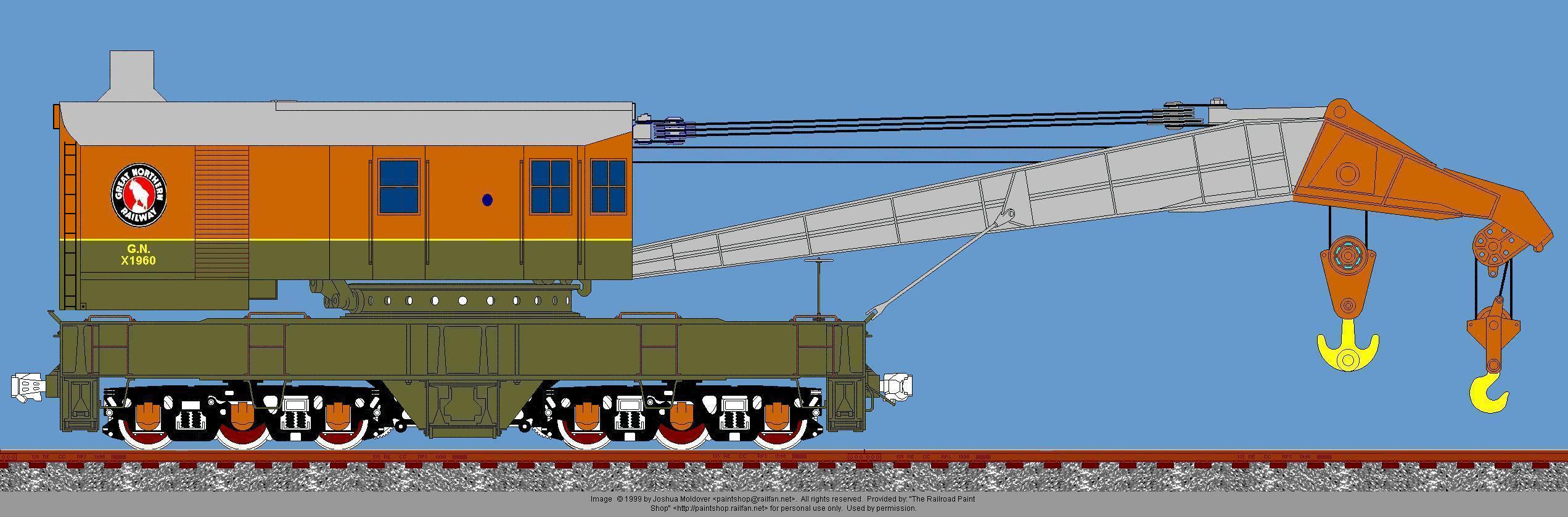
I began considering doing something more with a second Athearn 200t Railaroad Crane I had in storage. It was a plain black PRR one, so it was a good "blank canvas" to start from. I read the Aug 2012 MRH article by Dr. Geoff Bunza where he motorized his crane using miniature motors and a DCC circuit and sound board. To best appreciate his work, I believe there is a YouTube video by him showing the animation in action.Alas, I am not an electrical engineer, as is Geoff, but found his inclusion of lighting and certain design/style elements interesting. So, off I went to make my improved model crane (improved over the original MOW one I built and detailed for my Minnesota, Sioux Lake and Western). This time, the crane will represent a fictitious Great Northern railroad crane, using a color scheme that might have been applied- the colors are RGB-referenced from the Trainz website list of color codes, but I have the actual Polly Scale colors for airbrushing, so these might be approximate at best:
As I only wanted to add lighting, my other thread in Loose Ends about the constant lighting circuit design was critical to understand what I wanted to do in the inside- and outside.
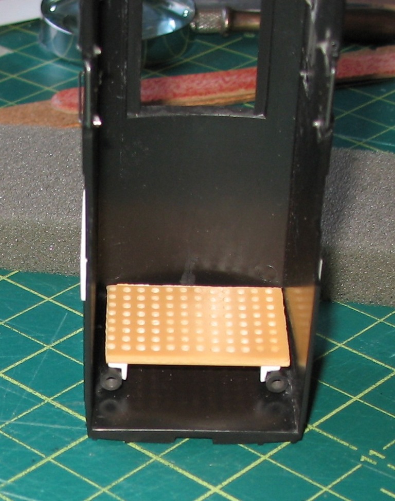
This image shows the modifications to the cabin, so far:
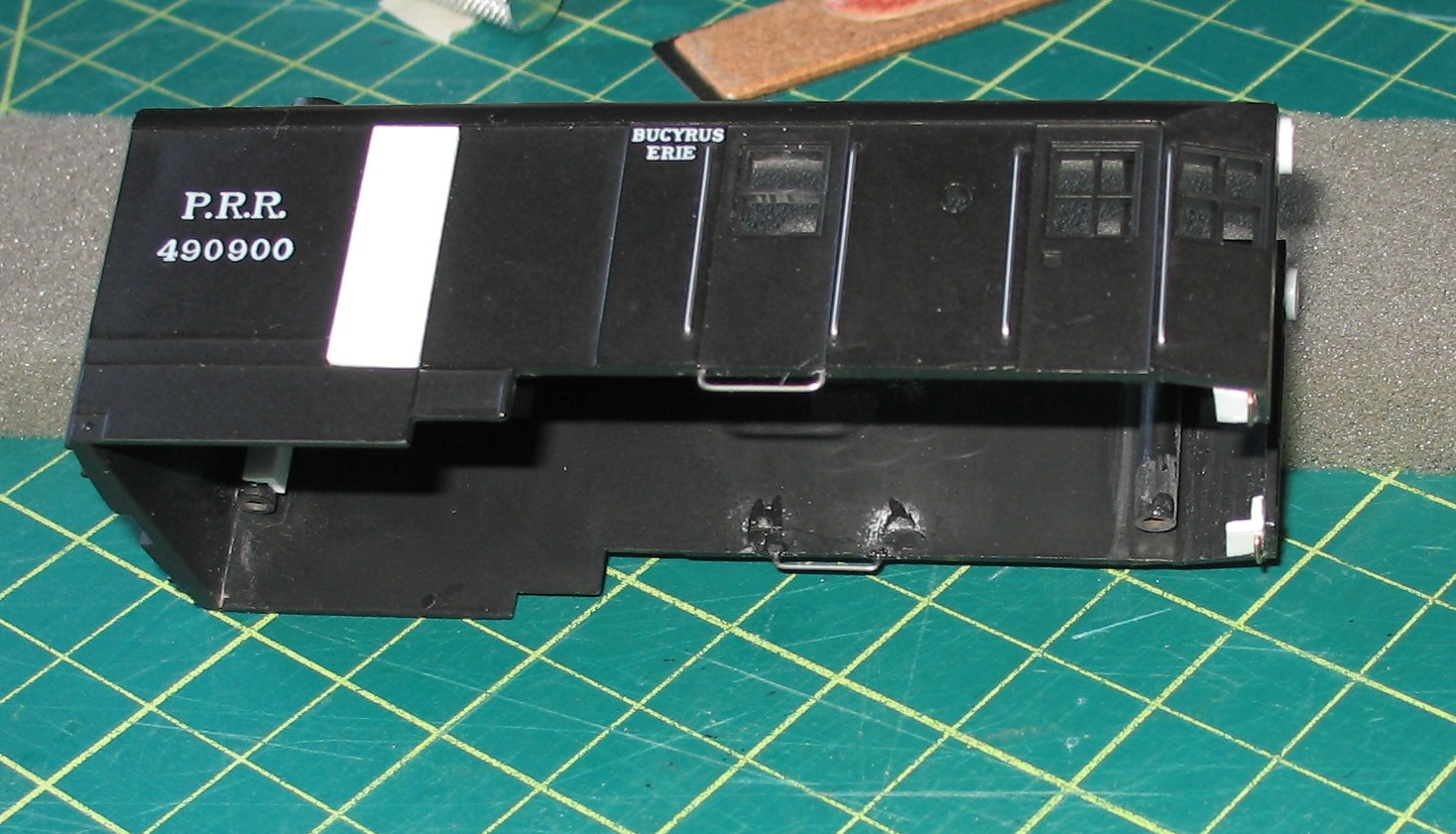
The white blurred plastic at the rear is 1/16" spacing clapboard, to represent louvers. I covered the rear doors completely; it also will mitigate wayward light from the rear LED. This is similar to screens and louvers placed on diesel-converted cranes in the 1950s, so my little fiction will be that the roof exhaust is for the diesel fumes and the side louvers serve to aid in cooling (summer) and heat retention duirng those frigid Minnesota prairie winters. All necessary grab rails were cut from .020 steel wire and CA-ed in place. I used a series of masking tape criss-cross strips to accurately locate holes. At the front end, simple angle flanges reinforced the front end before I drilled and mounted the front step rails.
The center window was modified as a double-hung one, since no one would be using it, except for maintenance when the crane was inactive.
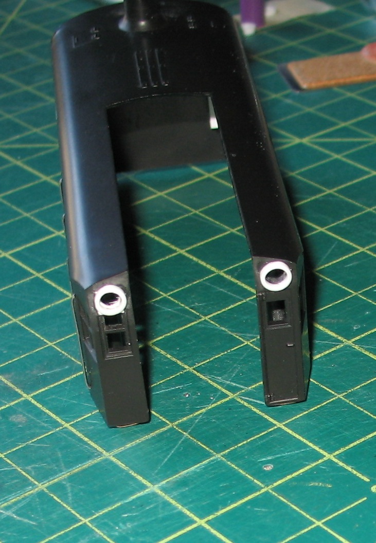
Up front, I cut 3" thick scale light housing rings from 3/16" tube by placing a smaller drill bit inside the tube and carefully rotating it in my hobby vise while cutting with a straightedge GEM blade. The drill bit kept the tube round and gave me a surface to cut against. I then drilled smaller holes (3mm) for the LEDs. The left side required a bit pf styrene to cover the top window opening first, so that the remaining frame cross pieces would not be harmed.

The rear light is also a 3mm LED size with the same 3/16" ring, but image research of real cranes showed various larger housings, so I found a bit larger styrene pen tube and used that as a "surround" to set it off in such a way.
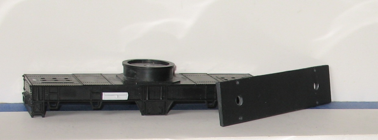
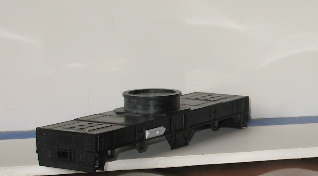
My experience with the first crane was that you can never have enough weight to keep this model stable, and I repeated my "mash-up" of a fishing weight for the center of the turret (with a hole for truck pickup electrical wires this time), but also added an exact-sized duplicate of the model's steel weight made from lead sheet (actually, a Home Depot lead roof boot cut and flattened into strips). I drilled the same screw holes as the steel weight and just used double stick tape to secure both together, as screw holes will hold the unit to the chassis. The electrical pickup wires will easily route underneath this weight thru the center weight turret hole, as the weight, when attached, stands off from the underside of the chassis by 1/8th inch. I also saw a side mounted tool box on one research photo:
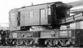
Although there are several shown on the side of the crane's chassis in this image, I figured that the boom car (I will also kitbash later) would also have much more storage capacity, so I included only one (angled similarly) on each side. This will also allow me to put appropriate decals in the open areas along each side.
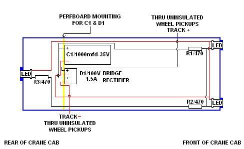
The lighting circuit will use a bridge rectifier diode (small) and a capacitor (3/4" long/tall), so I decided to mount them and the wiring connectors on a small perf board sideways, as the roof clearance is not sufficient. I used two small angle flanges as support surfaces (and to add a bit of additional clearance for the rear LED wire leads) mounted on the two molded rear screw housings for the perf board. I plan to use either spade or 2-wire male/female connectors to enable the cabin to come off the base, to access the cable string winches assemble, if needed.
I will now be primering the cabin and the chassis, then let that sit for a few days as I address the intial electronics work- besides, got to get back to work this week in the real world!
Once more, I am including my location diagram for the electronics in the hope that one of you wiser heads can review it to see if I am planning the physical wiring and connection of all electronics parts correctly:
More to come on this project!
Siouxlake Ron
Edited by - siouxlake on December 01 2013 3:10:48 PM
|
Country:  USA ~
Posts: 510 ~
Member Since: September 21 2011 ~
Last Visit: December 21 2014 USA ~
Posts: 510 ~
Member Since: September 21 2011 ~
Last Visit: December 21 2014
|
 Alert Moderator
|
|
|
|
Posted - December 01 2013 : 4:02:40 PM
|
| Great photo story Ron. Nice creative model work. I'll be looking forward to seeing and reading more of this project. Thanks. Barry
|
|
Country: USA ~
Posts: 2087 ~
Member Since: March 16 2013 ~
Last Visit: July 05 2018
|
Alert Moderator

|
|
|
|
|
|
