|
|
 Posted - January 12 2013 : 11:04:03 AM Posted - January 12 2013 : 11:04:03 AM


|
I managed to wrap a small brass wire around the rear axle on one (1) outside location. It turned out that 2 of them made the axle too tight, so one was used. I had already thoroughly cleaned and degreased the gears and cleaned the wheels. Using Mercon II ATF fluid as my preferred non-greasy lube, I then also placed a small piece of double-stick foam tape under the cylinder piece, to stabilize it- it will be easily compressed by the front smokestack screw, but the idea is to eliminate any looseness, as the acetal- to acetal plastic fit acts slippery.
Here is a photo of the work done:
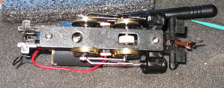
I attached a cheap plastic coupler to the chassis to test pulling power against vibration.
Using my cheap TYCO power pack attached to my test track strip, I found that the side-to side shimmy has been reduced significantly, but the engine (with boiler weight sitting on top of the gearing) is a bit hesitant at very slow speeds- under the "20" index mark on the power pack. I may hook up my MRC with momentum and pulse control to use a more sophisticated control and test again, but so far the results are very good overall.
I drilled out the rear light (use 1/8th inch drill and 3 mm flat LED- fits perfectly) and will wire the lighting front and rear later today. With the LEDS, I am using 470 ohm resistors.
One item, before I check myself, is the top of the motor (as originally installed) the positive lead or the negative lead?
I can find this out myself, before I wore the LEDS, but perhaps this is intuitive for someone to answer.
Will comment back later.
Siouxlake/Ron
|
Country:  USA ~
Posts: 510 ~
Member Since: September 21 2011 ~
Last Visit: December 21 2014 USA ~
Posts: 510 ~
Member Since: September 21 2011 ~
Last Visit: December 21 2014
|
 Alert Moderator
|
|
|
|
Posted - January 13 2013 : 01:29:58 AM
|
The right rail is always positive in the forward direction, so you can trace it from there. I see what you mean about the lateral slop. I don't think my older version had anywhere near that side-to-side play.
The Tyco Depot
|
|
Country: USA ~
Posts: 3927 ~
Member Since: June 20 2007 ~
Last Visit: November 19 2015
|
Alert Moderator

|
|
|
|
Posted - January 14 2013 : 08:06:19 AM


|
Ron,
The short lead to the LED is the Cathode and the long one isn't so....(Negative feed), the long lead of the LED is the Anode, (Positive Feed)
a 470 OHM resistor should work GREAT! Thats the rating I normally use unless its DCC...
~John
Many have tried to, and failed, ya just can't repair stupid... 
Do NOT try to Idiot-Proof anything!!!! God, will simply create a better......IDIOT!
|
|
Country: USA ~
Posts: 2911 ~
Member Since: March 26 2012 ~
Last Visit: January 14 2014
|
Alert Moderator
|
|