|
|
 Posted - November 27 2011 : 12:40:08 PM Posted - November 27 2011 : 12:40:08 PM


|
I am finally about ready (as the paint dries) to tell my summary story of my AHM Center Cab Rebuild project, which has consumed me these past 2 months. It is my first rebuild, and I am using it as a learning device with respect to a number of practices, so if I explain things a bit too much, also bear with me. Perhaps it may be somewhat elementary to other forum members, but someone else may come across it and benefit from my experiences.
I am practicing uploading an image to ensure that I understand the process as detailed in the forum help section. Ok- the preview looks good.
I am going to do this in several short segments- not to draw it out, but to make it easier for me to do this, given periodic household interruptions (the dog and his need to be accomodated, the daughter and her homework, the wife and instructions I must obey- but not necessarily in that order!).
Now for the initial commentary:
I was at a local flea market swap meet in early September and wanted to get another Plymouth MDT switcher, as I already had one that I wanted to restore. I did find one, but also came across an old AHM Center Cab diesel that "sort of" ran when tested on site at the flea market. I figured that this would also be a great addition to my small engine servicing facility/small freight yard layout. In addition, I could repaint it for my own local railroad.
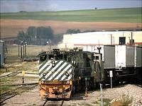
This is an internet image of the original (new) center cab with the ATSF livery that my purchase also had. Amazingly, mine was fairly clean (except for missing side railings) and I bought it for a whole $5.00!
Ron
|
Country:  USA ~
Posts: 510 ~
Member Since: September 21 2011 ~
Last Visit: December 21 2014 USA ~
Posts: 510 ~
Member Since: September 21 2011 ~
Last Visit: December 21 2014
|
 Alert Moderator
|
|
|
|
Posted - November 27 2011 : 1:42:56 PM
|
AHM Center Cab Rebuild Part 2:
I then wanted more info on the AHM Center Cab and that internet search brought me to this Tyco Forum, as the search query "AHM Center Cab" found a rebuilding article by ChrisC on the very same one I had just bought! Not only that, but his modifications appeared to give more "character" to the small diesel and others' comments back to him included a tip by Nelson (NKP) about replacing the plastic worm with a metal one to improve operability.
So I joined the forum and started the rebuild process.
When I took off the shell, I expected nothing good, but found the chassis to be fairly full of crud and metal fibers, as if someone had tried to clean something with steel wool. In addition, the wiring looked old and not well-concected at the solder points. The wheels were full of crud as well.
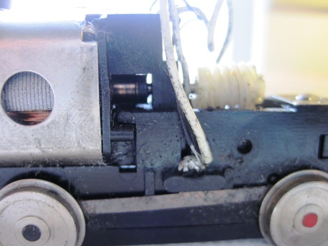
Amazingly, the motor appeared relatively clean, although where the brushes rotated was dirty.
I started out by disassembling everything, including clipping the original wires from the motor and used 400 wet/dry paper to clean the wheels first, both faces and rims. Then I cleaned the metal wheel wipes also, using the same paper.
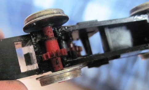
I took the gears from the gearbox and used dishsoap to clean them and the gearbox parts.
I followed this with 91% alcohol to catch any grease/crud I missed the first time.
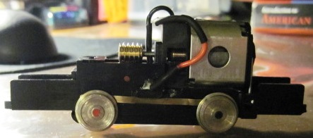
After conferring with Nelson about repowering, I ordered the same brass worm from an EBay seller, where I got 4 of them on 2mm shafts for about $9.00. I was not willing to spend $30+ to repower the engine, if the motor was still functional and in good shape. Testing the unit after the initial cleaning showed that it ran quite well- perhaps too well!
The issue with the original worm and gear ratios is that the diesel ran at warp speed- highly unrealistic for yard operations. I am not yet into DCC, and the limited space inside the shell would tend to discourage use of a board in the small space, anyway. The brass worm reduced the gearing ratio significantly. I have a test track with a small TYCO trainset power pack attached, which is not too precise, but the control over speed and the model's response
after cleaning and rewiting- and "re-worming" was amazing! (Note: I replaced the original weights back on the chassis before testing)
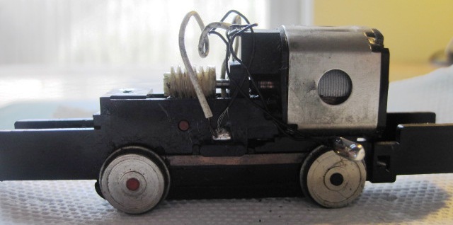
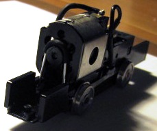
Here is an image of the cleaned up/rewired power chassis, with the new worm installed:
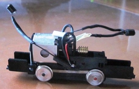
Next up, I saw that there were light lenses at both ends of the shell, but only one end (front) had a standard bulb wired in. Reasoning that safer operation might be obtained by having both front and rear lenses lit, I set about to use LEDs to do just that.
Last Christmas, I was tipped off (in an RMC article) to a set of 50 warm white 5mm LEDs on a string that was available at Walgreens for $5.00. Great Tip, as I was then doing a lot of structure building and lighting at the time and didn't want to pay big bucks for just a few LEDs, whether it be from a local Radio Shack or from an online source, so I grabbed them up! I still have over 35 of the m and saw them on sale again at the same price this year (2011), again at Walgreens.
I also read online about problems with "directional lighting" a I wanted to do. Some talked about a bridge rectifier and other electronic circuits, but again, space inside the shell was an insurmountable barrier. I had used a 470 ohm resistor (wired in series to the positive LED lead) in my buildings, but some other wise heads claimed a 1000 ohm (1K) was better. I tested both versions, using alligator clip connections, and found no noticeable difference in brightness (or none that I could see) between these 2 resistor values, so, as I had a bunch of 470 ohm ones, I stayed with what I knew.
Now the directional wiring issue was resolved by simply switching the connections on each LED, where they are soldered to the wheel wiper pickups. When I run in reverse, the rear LED lights, and when I run forward, the front one lights. (there is a small bit of current going thru the opposite LED, but it looks like a safety blinker effect, so that's okay). The front weight had a hole to allow the LED to shore thru, but I had to do a little sawing and gouging with a 1/4" chisel to enable the rear LED and wire to seat properly, without preventing the shell from being secured back on the chassis.
I will show that in the next upload message, as I have just hit the max on this one.
Ron
|
|
Country: USA ~
Posts: 510 ~
Member Since: September 21 2011 ~
Last Visit: December 21 2014
|
Alert Moderator

|
|
|
|
Posted - November 27 2011 : 2:01:40 PM
|
AHM Center Cab Rebuild-3:
Here's the final wired chassis image I could not upload on the last message:
A couple of pointers:
- I twisted and tinned each bare wire before soldering to the motor and the wheel wipers, as well as used shrink tubing to neaten things up and protect connections from dirt.
- I used a larger size of shrink tubing on the sides of the LEDs, to avoid light spillage back into the cab.
- you will also notice (when you see them) that the car weights are painted black for the same purpose.
- the shell has open grills at each side towards the ends, but when I tried using very thin styrene to cover them from the inside (to avoid excess light), they interfered with the closure of the shell onto the chassis. I figured the black painted car weights and the covered sides of the LEDs would suffice.
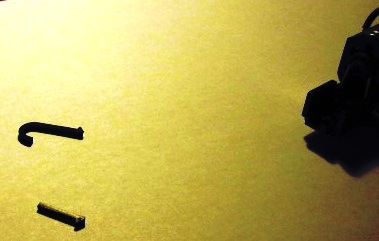
Along the way to remounting the motor, I managed to break the old plastic clip that held the rear of the motor in place. I was thinking of using foam stick tape, but saw a large sized paper clip nearby, and it fit the diameter of the rear shaft mount. A bit of shrink tubing to give a friction fit, a bit of slipping and beding the ends to go into each side clip hole and, as the French say "Voila", I had a new improved motor clip! Just to be safe, I used commercial double-stick tape (very thin- I use it to secure drafting board vinyl covers at school) to mount the motor bottom in the curved cradle. I tried double-stick foam tape, but the slight height difference created caused meshing problems with the motor shaft worm and the top gear of the gearbox.
Here is the mistake and the solution of the motor mount clip:
|
|
Country: USA ~
Posts: 510 ~
Member Since: September 21 2011 ~
Last Visit: December 21 2014
|
Alert Moderator
|
|
|
|
Posted - November 27 2011 : 2:41:48 PM
|
AHM Center Cab Rebuild-4:
With the power chassis completed and tested, I then turned my attention to the lower deck, to which the power chassis attaches. Chris C did an excellent job of painting, but where he used a blue color for both the lower deck and the shell/cab, I wanted to use my chosen railroad colors. The lower deck was a Delrin plastic. I had cut off the remaining front and rear railings, as two stanchions were already broken, so I primed the lower deck with good old Walmart Colormate Gray primer, which I used on many structures (all of them actually).
I read on the MR forums about difficulties with painting Delrin, due to it's slippery texture, but when I primed the lower deck as a whole, I let it sit for a week to "settle" and found no issues with the grab that the paiint had on the plastic. Perhaps the railings were Delrin, as was the power chassis and gears, but the deck was styrene? I know both types if plastics can be mated in the molding process, but the end result was satisfactory for me. I completely removed the railings and the residual parts along the sides of the lower deck. (no OSHA or FRA exists in my railroad's world- or at least not where a rebuilt switcher is concerned!)
Chris C had added some enhancements to the original model, and I took most of my cues from him (with exceptions, as noted) not wanted to copy him completely:
1. I also added storage boxes at each end of the lower deck, but used scribed stryene and a small latch piece, to give a different look to them.
2. I painted the arch bar arms and springs engine black (Polly Scale acrylic) to set them off better from the Rustoleum red primer color (spray can) used as one of my railroad's colors. I then used GN Orange (Polly Scale again) to highlight the edges and ladders/steps of the lower deck.
3. I used Walmart generic staples for the lower grabs (ala ChrisC), also painted GN Orange. These were loacted with a paper template and then drilled with a #70 bit in a hand vise). The ends of the grabs/staples were then clipped so they wouldn't show behind the steps.
4. I copied what ChrisC did and removed the original front steps, replacing them with styrene angles, but also added a pair to the rear end of the deck as well, reasoning they (and another set of grabs) would be useful in back and forth yard movements on my layout.
5. Finally, the original toy train couplers disappeared and I got a pair of #37 offset Kadees to mount as replacements, using a handy coupler height jig that I built (from a recent MR article by Jim Hediger) to properly gauge them. I got some 2-56 screws from Radio Shack and used
2-56 nuts to secure the couplers, after cutting off the original toy train coupler center post at each end. I used Kadee coupler box covers with some careful enlarging of the original coupler housing on the power chassis ends along with the screws and nuts.
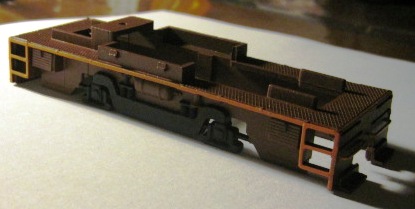
This is the final result of the lower deck rebuild and painting:
Having some trouble with the other images for this installment- be back when they are ready to upload (and after a few errands!)
Ron
|
|
Country: USA ~
Posts: 510 ~
Member Since: September 21 2011 ~
Last Visit: December 21 2014
|
Alert Moderator
|
|
|
|
Posted - November 27 2011 : 2:50:40 PM
|
Very Nice! Ill work on mine over Christmas break hopefully.
|
|
Country: USA ~
Posts: 1102 ~
Member Since: July 28 2011 ~
Last Visit: July 01 2015
|
Alert Moderator
|
|
|
|
Posted - November 27 2011 : 6:20:51 PM
|
Nice work, and nice tutorial, Ron! I too have turned to the lowly paper clip when looking to secure motors in projects like this, lol.
Just one note: the frame with handrails are one styrene casting, which is why they snap off like they do. If they were Delrin, they would flex. You can actually use CA or solvent glue to repair them, but the bond will be weak due to the lack of surface area. The only AHM diesel to have Delrin railings was the RS-2.
The Tyco Depot
|
|
Country: USA ~
Posts: 3927 ~
Member Since: June 20 2007 ~
Last Visit: November 19 2015
|
Alert Moderator
|
|
|
|
Posted - November 27 2011 : 10:44:40 PM
|
SL:
Particularly like the #3 idea with the staples but Sans the Hellmart version. Evil company! 
-Gareth
"A is A"
-Aristotle
Law of Identification
|
Country:  Canada ~
Posts: 4200 ~
Member Since: January 08 2006 ~
Last Visit: November 09 2021 Canada ~
Posts: 4200 ~
Member Since: January 08 2006 ~
Last Visit: November 09 2021
|
Alert Moderator
|
|
|
|
Posted - November 27 2011 : 11:06:27 PM
|
| This is good for me because I just posted a similar loco in the LOTW. Now I'll know what to expect if I need to open it up.
|
|
Country: USA ~
Posts: 1166 ~
Member Since: October 18 2009 ~
Last Visit: December 23 2018
|
Alert Moderator
|
|
|
|
|
|