|
|
 Posted - June 03 2011 : 7:31:58 PM Posted - June 03 2011 : 7:31:58 PM


|
how do I do a constant voltage headlight? I'm needing to replace a bunch of headlights anyway, so I thought this would be a good time to do the constant voltage headlight conversion. What are the formulas, & why & how does it work?
jerry
|
Country:  USA ~
Posts: 553 ~
Member Since: January 14 2009 ~
Last Visit: September 13 2024 USA ~
Posts: 553 ~
Member Since: January 14 2009 ~
Last Visit: September 13 2024
|
 Alert Moderator
|
|
|
RETRO
Switcher

Status:
offline
| |
Posted - June 16 2011 : 9:16:52 PM
|
Hello Jerry
to move your train slow it takes ,let say 3 volts
to move your train fast , 12 volts
so you are going to have the lights go dull & bright no matter what you do apart from going DCC which gives you 12 volts all the time and with the abillity to tone them down as well
unless somebody has conected a capasiter to hold a charge at 12 volts and feed it gradually and not at a short belt
RETRO.
BEEN THERE, DONE THAT, WHATS NEXT !
|
Country:  Australia ~
Posts: 25 ~
Member Since: June 15 2011 ~
Last Visit: April 09 2013 Australia ~
Posts: 25 ~
Member Since: June 15 2011 ~
Last Visit: April 09 2013
|
Alert Moderator

|
|
|
|
Posted - June 17 2011 : 1:02:03 PM
|
Constant voltage headlights are possible with regular DC locomotives. I have made several.
You need 4 diodes or a bridge rectifier. I do not know how you show you unless I take a photo of the wiring diagram and submit it to the forum. They are wired in parallel with your motors armature, and you will be using 1.5 volt bulbs. Try a search for past Model Railroader articles.
Unspoken expectations are premeditated failures.
|
|
Country: USA ~
Posts: 825 ~
Member Since: December 22 2008 ~
Last Visit: March 16 2015
|
Alert Moderator
|
|
|
|
Posted - June 17 2011 : 2:22:52 PM
|
never mind the bulbs  Use a LED! Use a LED! 
|
|
Country: USA ~
Posts: 15031 ~
Member Since: February 23 2009 ~
Last Visit: July 07 2026
|
Alert Moderator
|
|
|
|
Posted - June 17 2011 : 8:59:56 PM
|
quote:Constant voltage headlights are possible with regular DC locomotives. I have made several.
You need 4 diodes or a bridge rectifier. I do not know how you show you unless I take a photo of the wiring diagram and submit it to the forum. They are wired in parallel with your motors armature, and you will be using 1.5 volt bulbs. Try a search for past Model Railroader articles.
Originally posted by NC shortlines - June 17 2011 : 1:02:03 PM
|
would you please take a photo of the wiring diagram and submit it to the forum? or one of an engine that has had it done.
jerry
|
|
Country: USA ~
Posts: 553 ~
Member Since: January 14 2009 ~
Last Visit: September 13 2024
|
Alert Moderator
|
|
|
|
Posted - June 23 2011 : 12:30:49 PM
|
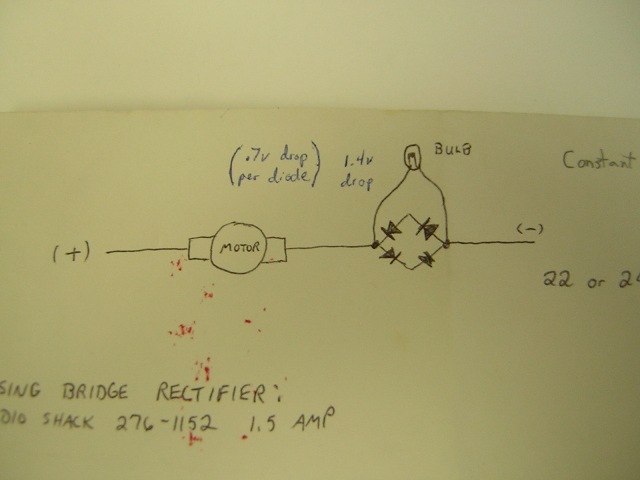
Here is the diagram for the constant lighting. The diodes are typical from Radio Shack,
I think they are 1N004 or something like that.
Unspoken expectations are premeditated failures.
|
|
Country: USA ~
Posts: 825 ~
Member Since: December 22 2008 ~
Last Visit: March 16 2015
|
Alert Moderator
|
|
|
|
Posted - June 23 2011 : 4:24:29 PM
|
i see it, but i don't understand it.
jerry
|
|
Country: USA ~
Posts: 553 ~
Member Since: January 14 2009 ~
Last Visit: September 13 2024
|
Alert Moderator
|
|
|
|
Posted - June 23 2011 : 10:40:47 PM
|
It might be a little confusing because some of the words apply to another drawing.
Take 4 standard diodes, 1N1004, can't remember the exact part number, but they are black diodes with a silver band. Common Radio Shack stuff. Lay the four diodes side by side, alternating their direction. You don't have to solder them in a square, that's just for schematic purposes but, you could put it together just like the drawing. YOu solder them nose to tail, nose to tail. Let's say diode 1 is at the upper left in the drawing, diode 2 is lower left. 10 o'clock and 7 o'clock positions. solder one lead of a 1.5volt bulb in between diode 1 and 2. The other bulb wire will go between diodes 3 and 4. Cut the negative wire on your motor and solder in the diode pack you just made. Which is the negative wire? you might ask, doesn't polarity change with direction? YES. The negative wire should be the wire that connects to the left wheels;when the loco is going forward. If you pick the wrong wire, the only problem is the lights will only illuminate when in the loco is in REVERSE. Not pictured in the diagram are the wheels of the loco. But they would be at the ends of the wires marked + and -..
The way this works is: although voltage varies with speed/power, the voltage drop across the diodes is fairly constant at 1.4 volts. Hence the bulb only "sees" the drop and stays constantly illuminated. It will vary brightness some or flicker. Particularly with cheap motors.
IT will work, even on the old PowerTorque motor. Got a couple of locos modified this way.
|
|
Country: USA ~
Posts: 825 ~
Member Since: December 22 2008 ~
Last Visit: March 16 2015
|
Alert Moderator
|
|
|
|
Posted - June 23 2011 : 10:43:47 PM
|
| By the way, forget what I said about being in parallel with the motors armature. The diodes are in series with the motor. Been several years since I did this and I don't have a loco handy to look at.
|
|
Country: USA ~
Posts: 825 ~
Member Since: December 22 2008 ~
Last Visit: March 16 2015
|
Alert Moderator
|
|
|
|
Posted - June 24 2011 : 01:59:51 AM

|
ok question on the circut....how would this apply to an LED?
just me Ray... and just because I have Tyco doesn't mean I am not a model railroader
|
|
Country: USA ~
Posts: 506 ~
Member Since: April 03 2011 ~
Last Visit: November 29 2025
|
Alert Moderator
|
|
|
|
Posted - June 24 2011 : 07:21:42 AM

|
quote:ok question on the circut....how would this apply to an LED?
Originally posted by rgcw5 - June 24 2011 : 01:59:51 AM
|
An LED is a different animal, because you don't want polarity reversing thru it constantly. It may not hurt it, I'll ask my engineer at work today, but it'd only light one way, not both forward and reverse. With a standard bulb, it's ok to switch polarity back and forth, it's just a dumb filament.
Jerry
" When life throws you bananas...it's easy to slip up"
|
|
Country: USA ~
Posts: 3974 ~
Member Since: January 04 2009 ~
Last Visit: January 11 2019
|
Alert Moderator
|
|
|
|
Posted - June 24 2011 : 07:27:45 AM
|
quote:i see it, but i don't understand it.
Originally posted by smokie - June 23 2011 : 4:24:29 PM
|
Diodes are simply one-way electrical "valves", the current will flow one way, but not the next. I use the analogy of the diode symbol >| or |< as funnels, or pointed arrows. The current flows in the directly of the arrow, or into the wide funnel opening and out the narrow end. Get it? If you look at the square, on one side a pair point one way on one side, and point the other way on the other. These you can reverse polarity on, they just prevent current flow thru them the opposite way. So if you attach a light to the middle connections, you get the current flow either way with a filament, but only one way with an LED. You could put two LEDs across it opposite each other, and one or the other will be lit ( forward or reverse light ). So probably an LED can have reverse polarity with no damage, I'm not sure on that, I'm used to circuits where they are constantly powered the correct way. I'll have to ask on this one.
Jerry
" When life throws you bananas...it's easy to slip up"
|
|
Country: USA ~
Posts: 3974 ~
Member Since: January 04 2009 ~
Last Visit: January 11 2019
|
Alert Moderator
|
|
|
TKRR
Switcher
Status:
offline
| |
Posted - June 25 2011 : 11:37:36 AM
|
NC and AMC are right on the money with this one.
The diode bridge will provide a fixed voltage drop for the light, granted that the supply voltage to the rails is greater than 1.5V. The only drawback is the small loss of voltage to the motor, but cranking the control knob a little farther fixes that!
If you want to use a white/yellow LED instead of the filament bulb, it may require a slight adjustment. (Possibly a current-limiting resistor or another rectifying diode in the bridge, to boost the voltage to the light.)
There are other circuits that could draw power directly from the rails while maintaining the light intensity. If there is interest, please give a yell. It would take about 6-10 basic components to hook it up. Meanwhile, the bridge circuit and bulb provide a very good solution.
-Todd
|
|
Country: USA ~
Posts: 72 ~
Member Since: January 17 2008 ~
Last Visit: November 20 2012
|
Alert Moderator
|
|
|
|
Posted - July 01 2011 : 07:41:31 AM
|
Ok,I asked my electronic Engineer at work , who designs circuits. Basically, most LEDs can NOT handle reverse CURRENT for very long, they will burn out! They're designed to function one way,and most work very poorly in a rectifier-type situation. Some LED's are available that have more current-limiting ability for that, and some do have rectifier capabilities, but for your generic, recycled types, they won't last long if you hook them up reversed for very long.
The solution? He said using the common 1N914 differential switching diode in series with the LED, and a small resistor for voltage limiting, will solve the problem. The 1N914 will limit the backflow of current sufficiently to stop the flow and prevent damage to the LED. So hooking up the LED to the top and bottom of that bridge rectifier circuit, just add in a 1N914 diode and a small ohm resistor, should take care of it. Values of the resistor will be determined by what LED you have to use, so experimentation will be necessary, could be anywhere from 20 to 100 ohms. And it doesn't matter which side of the LED it's on, as the current will stop at the diode, hence not flow thru the LED for long. DO want the resistor on the high voltage side, though.
As far as voltage, the 1N914 diode can handle up to 75 volts, so 12-14 VDC is no problem for it. Turn-on voltage ( at which point the diode permits flow ) is around 1 volt. Reverse voltage is limited to about 0.75 volts. That's what protects your LED from the reverse polarity and potential death-kill. And the 914 is a standard, off-the-shelf diode available easily.
As someone mentioned the 1N4001 / 4002 series diodes, that one is commonly used in the Rectifier Bridge circuit. The difference between the two is that the 4001/2 is a slower acting diode, the 914 is used more in data circuitry because it can switch faster, the 4001/2 is more often used in power situations where voltage change requirements aren't as critical ( ie, data streams require precise polarity changes, power handling does not ). Since you're just wanting a light, you can probably use the 4001 or 4002 ( -1 is 50 volt range, the 4002 is 75 volt range, I believe ). I think the 4001 and 2 allow more reverse current than the 914, though, which is probably why it's not as good a choice to use with the LED, the 914 will be the better choice here, I think, as it's more resistant <sic> to reverse current flow, which will kill an LED.
So, that's the circuit lesson for the day, I learned something myself having the engineer explain it. Hopefully you did , too.
Jerry
" When life throws you bananas...it's easy to slip up"
|
|
Country: USA ~
Posts: 3974 ~
Member Since: January 04 2009 ~
Last Visit: January 11 2019
|
Alert Moderator
|
|
|
|
Posted - July 01 2011 : 08:28:26 AM
|
very interesting info 
Not to get off topic But how do you do directional lights? Need to to do 4 on my MUNI Boeing LRV
|
|
Country: USA ~
Posts: 15031 ~
Member Since: February 23 2009 ~
Last Visit: July 07 2026
|
Alert Moderator
|
|
|
|
Posted - July 01 2011 : 6:52:16 PM
|
quote:very interesting info
Not to get off topic But how do you do directional lights? Need to to do 4 on my MUNI Boeing LRV
Originally posted by microbusss - July 01 2011 : 08:28:26 AM
|
Ben, that WAS my point, with LEDs. Directional lighting via rectifier circuit shown is fine, for LEDs you need additional diodes and possibly voltage-drop resistors to accomplish the same thing while protecting the non-reversing nature of LEDs. The topic started off as constant voltage, but morphed into the Rectified circuit, which will provide directional lighting for BULBS only, add additional 1N914 Diodes and small resistors to use LEDs. Clear now?  
Jerry
" When life throws you bananas...it's easy to slip up"
|
|
Country: USA ~
Posts: 3974 ~
Member Since: January 04 2009 ~
Last Visit: January 11 2019
|
Alert Moderator
|
|
|
|
Posted - July 02 2011 : 2:35:28 PM
|
if you want to learn about diodes go to www.kpsec.freeuk.com/led.htm
you can print it out.
If will help with all diodes.
Ken
FIDDLEHEAD RAILWAY CO.
|
Country:  Canada ~
Posts: 468 ~
Member Since: January 17 2010 ~
Last Visit: February 29 2012 Canada ~
Posts: 468 ~
Member Since: January 17 2010 ~
Last Visit: February 29 2012
|
Alert Moderator
|
|
|
|
Posted - July 02 2011 : 5:47:42 PM
|
I gave the wrong info.
Go to (the electronics club) on Google and you will get the info.
I found it very good.
Ken
FIDDLEHEAD RAILWAY CO.
|
|
Country: Canada ~
Posts: 468 ~
Member Since: January 17 2010 ~
Last Visit: February 29 2012
|
Alert Moderator
|
|