|
|
 Posted - July 11 2009 : 07:53:20 AM Posted - July 11 2009 : 07:53:20 AM


|
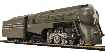
I have put together 90% of a Y6B from the 'bits bin'.
It has the die cast chassis plate for the round motor that is held by 2 screws in the motor front plate & the whole thing drops horizontally into a diecast 'half moon cradle for the screws.
Also has the dog leg Gbox/Dshaft set up.
The new motor is offset geared & the front plate screw holes do not line up for the Rivarossi chassis screw positions. Which means I am probably up for a silicone sealer 'glue in' job.
However, my query relates to the motor wiring.
I have wired the front truck per other examples I have of this Y6B, ie, 1 wire to a tag held down by the bolt holding valve gear support cradle & the other wire goes down a hole to a plate under the light bulb assembly, held by the bolt for the front pilot wheels.
I had the multimeter on the motor end of the bare wires [not hooked to the motor], last night while the chassis sat on live rails.
No reading.
I am not sure where the power pick ups & flows are in the Y6B & am wondering if the circuit is completed by the motor case, or should I run a tag to say a gearbox bolt to 'earth' the set up, as I saw in a Cab Fwd
re-motoring picture??
If someone could talk me through the power pickup system & tell me if I have something wrong here or am missing something, would appreciate it.
Thanks
Tanked.
|
Country:  USA ~
Posts: 243 ~
Member Since: September 08 2008 ~
Last Visit: January 04 2012 USA ~
Posts: 243 ~
Member Since: September 08 2008 ~
Last Visit: January 04 2012
|
 Alert Moderator
|
|
|
|
 Posted - July 11 2009 : 3:07:48 PM Posted - July 11 2009 : 3:07:48 PM


|
There are different versions of this engine, and the pickup varies between them. The older version that I have picks up power from one rail with the tender, and the opposite rail with the drivers. Your version has loco pickup only, with each set of drivers picking up power from opposite rails. I believe the rear drivers conduct current to the old motor through the boiler weight, and the wire from the lug on the front frame goes to the other motor brush.
You need to run the wire from the lug on the front set to one side of the motor, and connect the other motor terminal and the bulb wire to the boiler weight. You could solder the bulb wire and a wire for the motor to the brass lug that's riveted to the middle of it. Be sure the loco travels in the right direction before soldering the wires to the motor.
That should do it.
The Tyco Depot
|
Country:  USA ~
Posts: 3927 ~
Member Since: June 20 2007 ~
Last Visit: November 19 2015 USA ~
Posts: 3927 ~
Member Since: June 20 2007 ~
Last Visit: November 19 2015
|
 Alert Moderator

|
|
|
|
 Posted - July 11 2009 : 6:01:33 PM Posted - July 11 2009 : 6:01:33 PM


|
quote:
You need to run the wire from the lug on the front set to one side of the motor, and connect the other motor terminal and the bulb wire to the boiler weight. You could solder the bulb wire and a wire for the motor to the brass lug that's riveted to the middle of it. Be sure the loco travels in the right direction before soldering the wires to the motor.
That should do it.
Originally posted by NickelPlate759-July 11 2009: 3:07:48 PM
|
Thanks Nelson.
Will dummy that up & test it for direction & efficacy.
Tanked
|
Country:  USA ~
Posts: 243 ~
Member Since: September 08 2008 ~
Last Visit: January 04 2012 USA ~
Posts: 243 ~
Member Since: September 08 2008 ~
Last Visit: January 04 2012
|
 Alert Moderator

|
|

