|
|
 Posted - March 21 2009 : 3:37:00 PM Posted - March 21 2009 : 3:37:00 PM


|
Has anyone ever noticed the cover of the manual included with this system?
It seems confusing?
The way they have it going they have trains going against each other, in the wrong directions.
The outer track has the "Chatanooga" going in a counter-clockwise direction.
It also has an Amtrak GG-1 going in a clockwise direction on the opposite side of the same track.
Then there's a "Comin' Round The Mountain" engine on an inner siding facing as if it will also run on the outer spur in a clock wise direction.
Then there's a, what I believe is a, "Royal Blue" engine on the very inner circle with only one switch to let it enter, in the forward running position, the inner loop, counter-clockwise there too.
I guess my question, or statement, would be; Is, or was, all this possible to do {even in the 1970's era}?
It seems like a mistake on the part of the layout designers, or they just threw this whole thing together to get a cover shot, not caring if it actually worked or not.
Any input would certainly be appreciated  
Tyco Layout Expander System Large Covershot
|
Country:  USA ~
Posts: 16 ~
Member Since: February 24 2009 ~
Last Visit: February 03 2011 USA ~
Posts: 16 ~
Member Since: February 24 2009 ~
Last Visit: February 03 2011
|
 Alert Moderator
|
|
|
|
 Posted - March 21 2009 : 3:48:02 PM Posted - March 21 2009 : 3:48:02 PM
|
In a word... Yes. I believe with insulated rail joiners, controlling when power would be allowed to a certain part of the track, all of this could be possible, ablite somewhat annoying to today's standards. If you notice, there is A LOT of terminal tracks, connecting to different parts, all electrically blocked from each other. I believe that is what some of those buttons and levers control in the far back left of the snapshot...
...and by all means, those more experienced, correct me if I'm wrong, as you always do...
D.J. (Yeah, I'm "that kid"... Deal.)
http://railroadrandomness.blogspot.com/
Look; a new blog...
Yippee!
|
|
Country: USA ~
Posts: 157 ~
Member Since: February 05 2009 ~
Last Visit: June 05 2017
|
Alert Moderator

|
|
|
|
Posted - March 21 2009 : 5:56:50 PM

|
If you had the track "blocked" with insulated rail joiners like DJ said, than you could easily park one train on one of those sidings while the other ran in the opposite direction. Looking at that track layout though, I don't think you could run them both at the same time...or if you could, you'd be pushing buttons to block tracks and change switches every second or two
|
Country:  Canada ~
Posts: 3448 ~
Member Since: September 22 2006 ~
Last Visit: April 03 2026 Canada ~
Posts: 3448 ~
Member Since: September 22 2006 ~
Last Visit: April 03 2026
|
Alert Moderator
|
|
|
|
Posted - March 22 2009 : 10:53:09 PM
|
This was my first 4x8 layout. I started with the Spirit of 76 over and under set and bought the layout expander with the cash from the trusty paper route. I've attached a few scans from the instructions on the placement of the insulated rail joiners. Cheez & DJ are correct, the 2 on the outer loop can only be ran one at a time. The Tyco blocking controller handled the power distribution. Later I used an Atlas connector for that function. The two sidings and the coal dump were isolated with an Atlas connector as well. The inner loop was connected to the outer by 2 switches, insulater joiners on the connection at the 2 switches. It was a cool layout at the time.
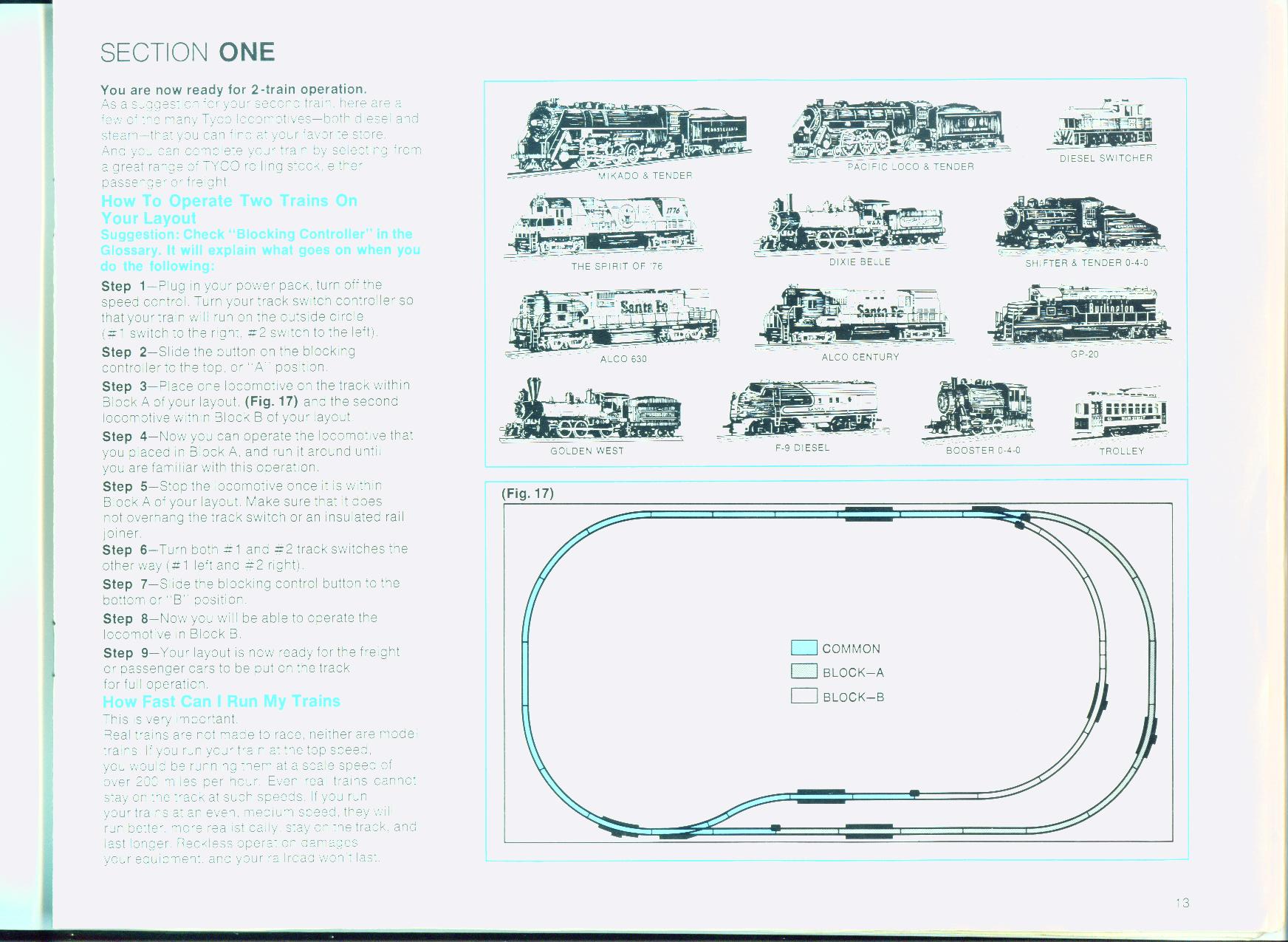
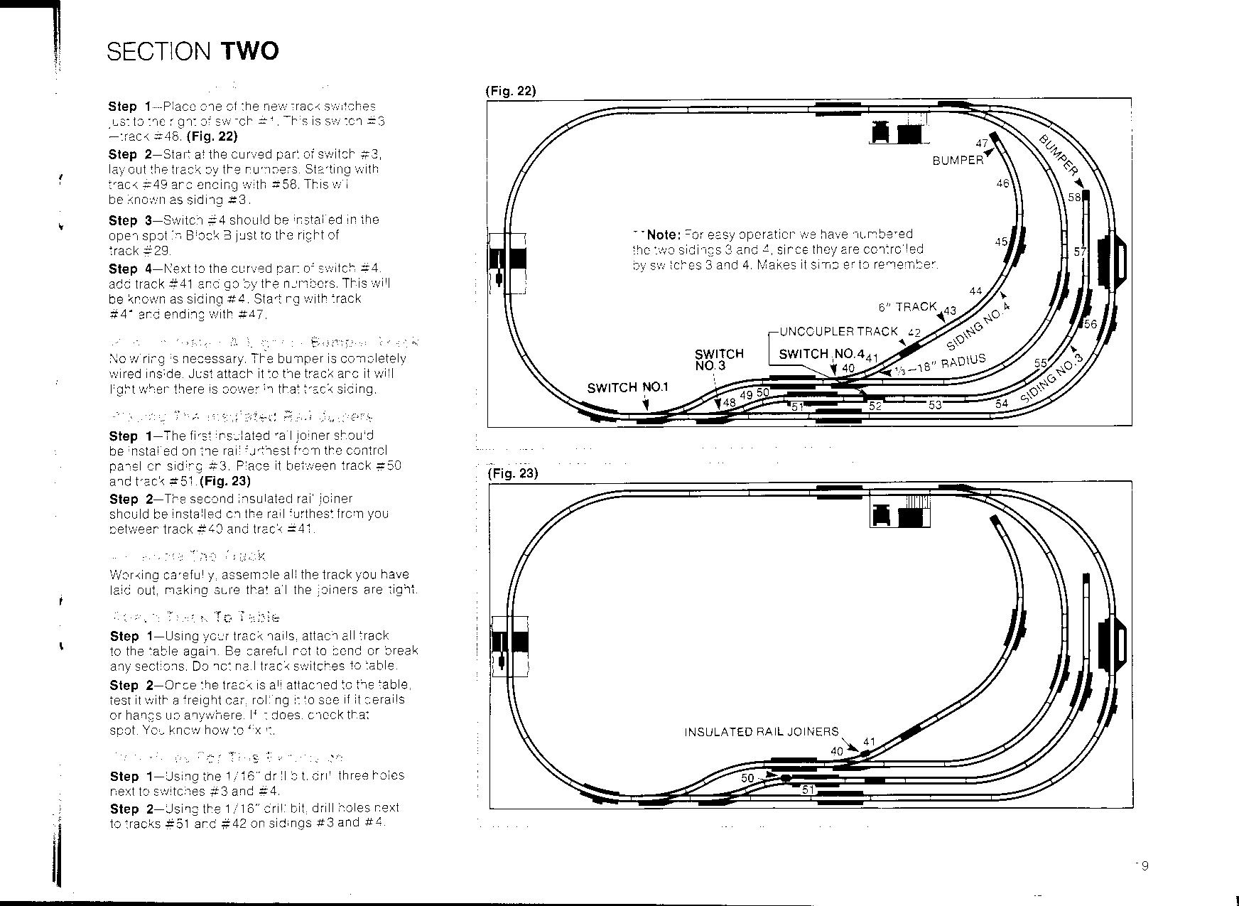
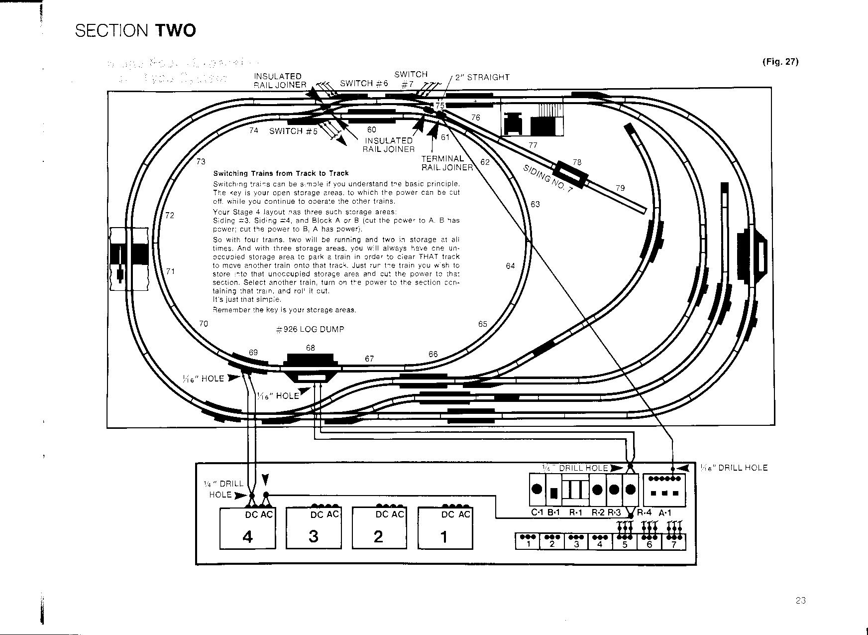
If you click on the image it makes it a larger size.
Tom
Edited by - eaglerock109 on March 22 2009 10:58:04 PM
|
|
Country: USA ~
Posts: 636 ~
Member Since: February 03 2008 ~
Last Visit: June 22 2026
|
Alert Moderator
|
|
|
|
Posted - March 23 2009 : 09:12:24 AM
|
| If you look at the cover photo of the Layout Expander booklet (the earlier one, at least), you will also notice that there are NO wires going to switch machines, accessories, or even coming from the power packs!
|
|
Country: USA ~
Posts: 874 ~
Member Since: October 15 2007 ~
Last Visit: June 09 2019
|
Alert Moderator
|
|
|
tod513
Switcher
Status:
offline
| |
Posted - March 23 2009 : 09:47:40 AM
|
I see the operating hopper but I don't see the operating box car, operating log transport car, flat car for the piggyback trailers or the skid flat car for the pipe load. I wonder why those were left out when there accessories were on the layout.
Edited by - tod513 on March 23 2009 12:14:48 PM
|
|
Country: USA ~
Posts: 45 ~
Member Since: March 08 2008 ~
Last Visit: November 05 2013
|
Alert Moderator
|
|
|
|
Posted - March 23 2009 : 9:42:46 PM
|
The scans I posted were from the "first edition" of the layout expander book. I call it first edition, it's the one with the white cover as opposed to the black back ground. There are other images in the book connected to wiring and accessory positioning, they could have moved them on the "second book". I'm on the road for work until Friday. If you'd like to see the others I'll scan them and post them when I get home.
Duh, I reread the previous comment and realized the cars for those accessories are missing from the photo, not my long winded wiring explaination. Sorry
Edited by - eaglerock109 on March 23 2009 9:45:32 PM
|
|
Country: USA ~
Posts: 636 ~
Member Since: February 03 2008 ~
Last Visit: June 22 2026
|
Alert Moderator
|
|