|
|
 Posted - May 23 2024 : 12:29:29 AM Posted - May 23 2024 : 12:29:29 AM


|
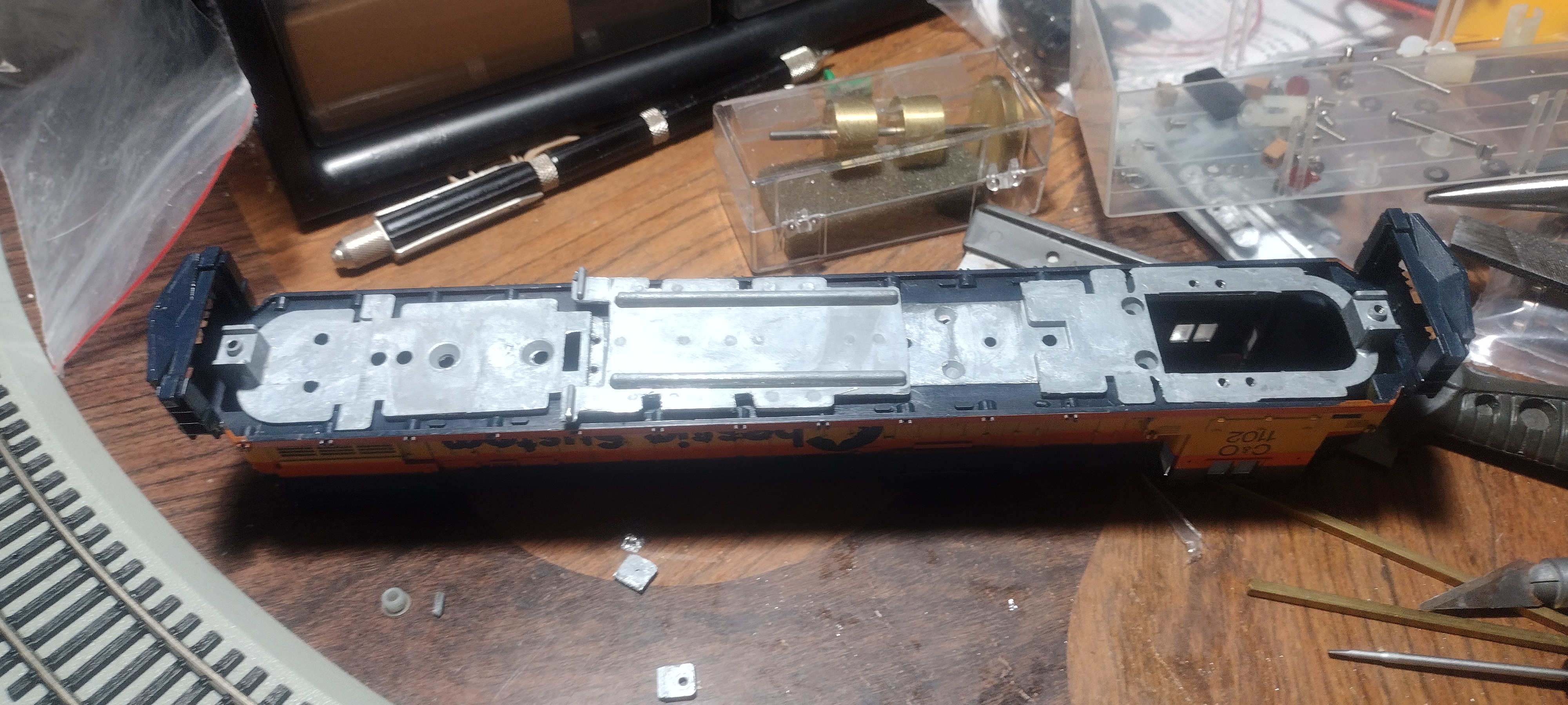
I recently started my Tyco C630 rebulld program. The photos below are of the first unit in the program. If it is successful, I have at least two more to do including a Golne Eagle.
I had considered a number of options including dual power torques, and replacing the magnets in the motor. In the end I opted not to use the Tyco drives for a couple of reasons. First and foremost was the traction tire issue. I don't like them, and don't want any on my motive power. That meant finding suitable replacement wheels for the ones grooved for tires. Even then, i'd have a locomotive with less than optimal electrical pickup, and no easy way to correct it.
I may revisit the dual power torque idea in the future, but as a battery powered dead rail locomotive where the pickup through the wheels won't matter. But cost is a factor here. Rebuilding a locomotive with a battery and Bluetooth control is twice as expensive as the solution I steeled on.
It turns out Hobbytown of Boston, a name long associated with smooth running locomotives going back at least 60 years, is still around. Better yet, they make a universal drive that not only has the option of the proper Alco trucks for the C640, it is also expandable in length to fit anything from an SD45 to a U28C. The C630 is slightly longer than the C630. Best of all, its cost of $75 is less than half the price of a new locomotive, What's not to like?
I have two C630s and a bunch of C430s that are candidates for this conversion. A similar universal kit is available for 4 axle diesels like the C430. One of my C630s is the Golden Eagle, and I didn't want to use that as a guinea pig, the Chessie System one is far more common and thus expendable should the conversion not work out as planned.
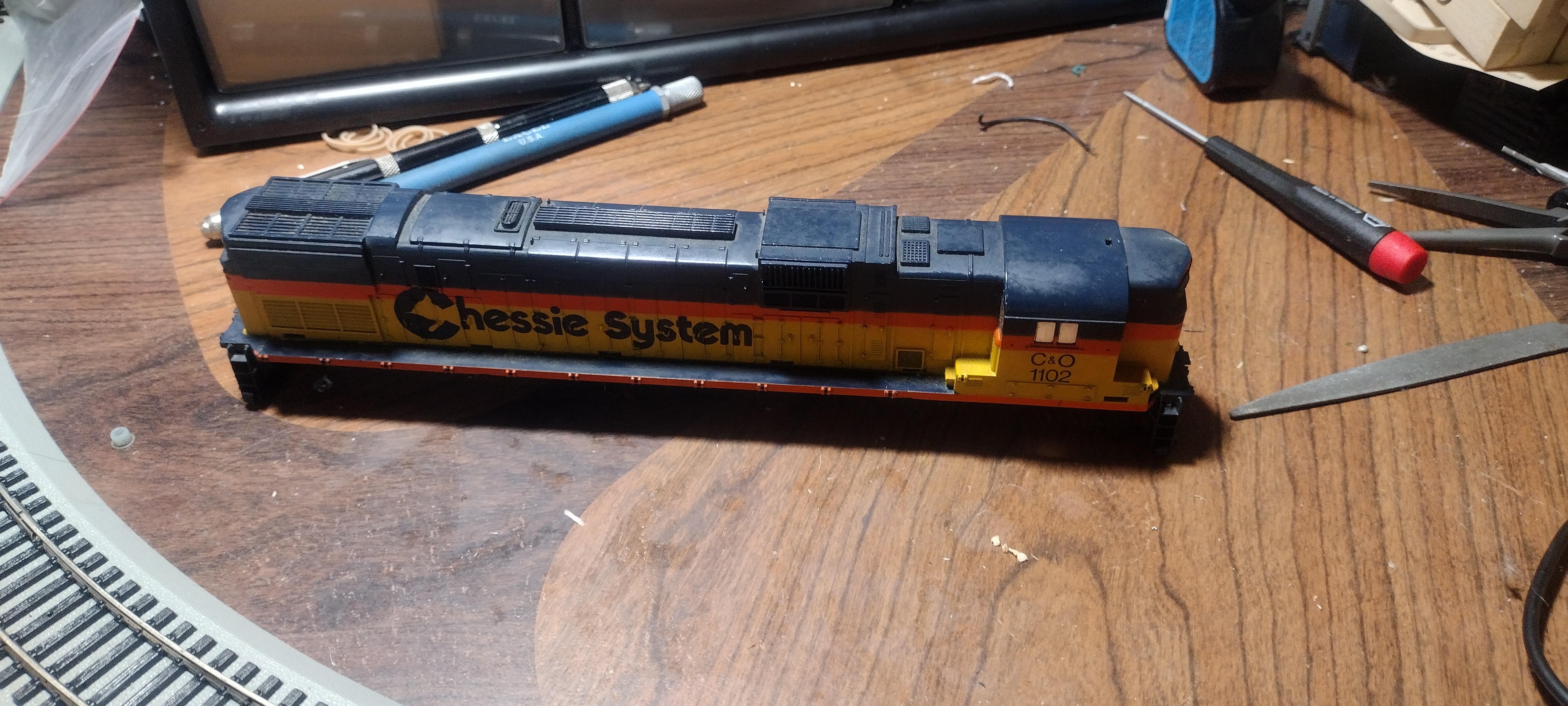
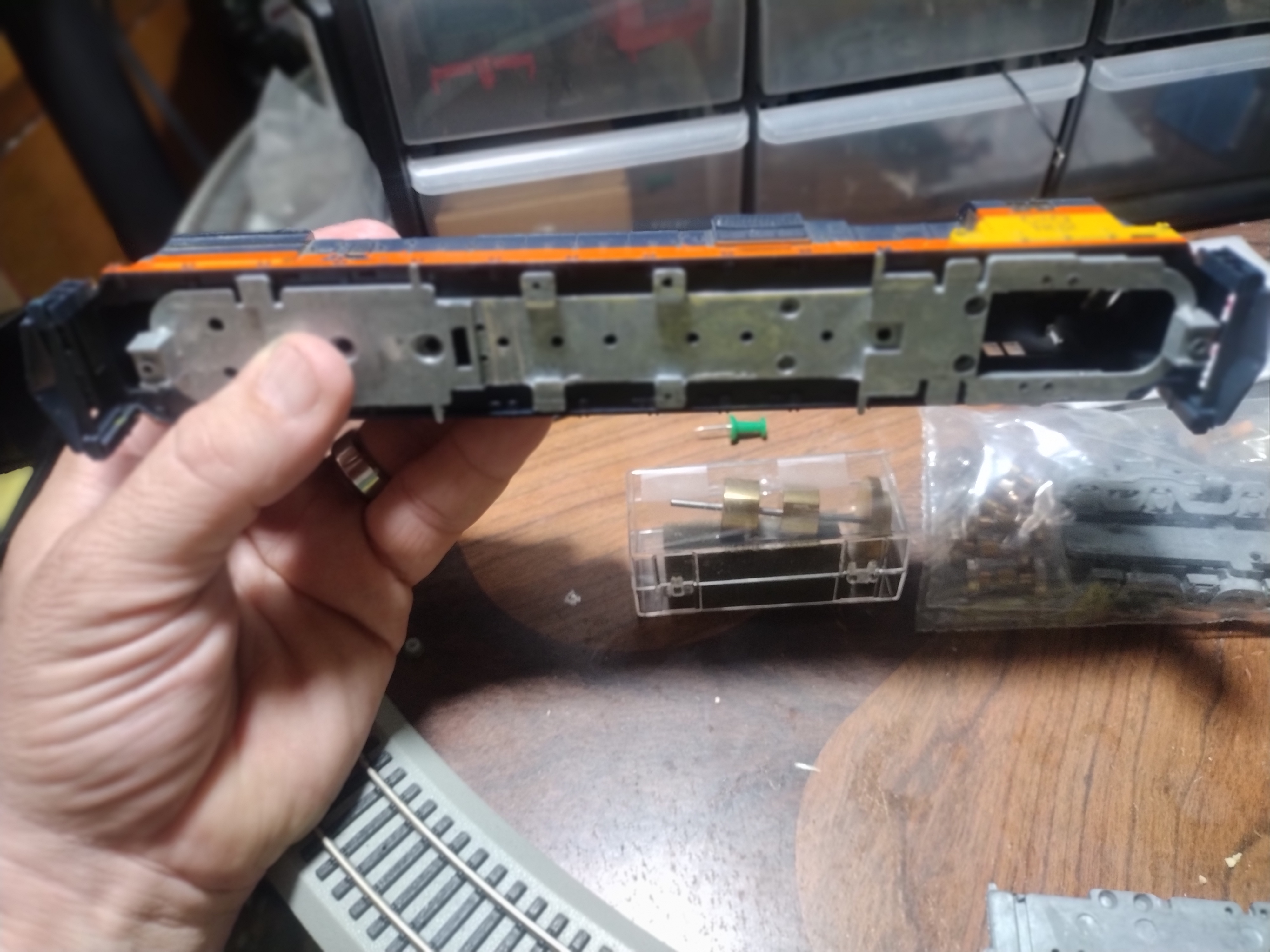
The donor locomotive. The power torque driver and fuel tank weight have already been removed.
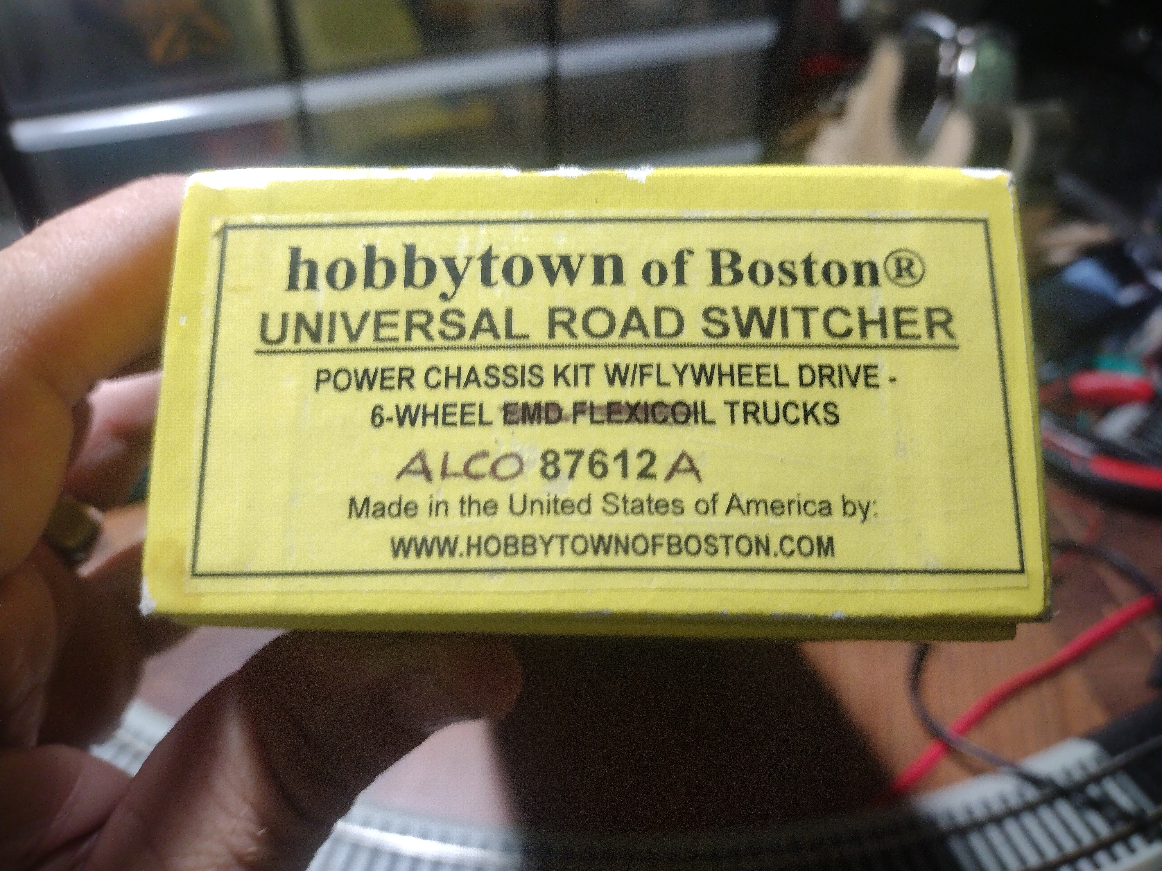
This is the kit used in the conversion.
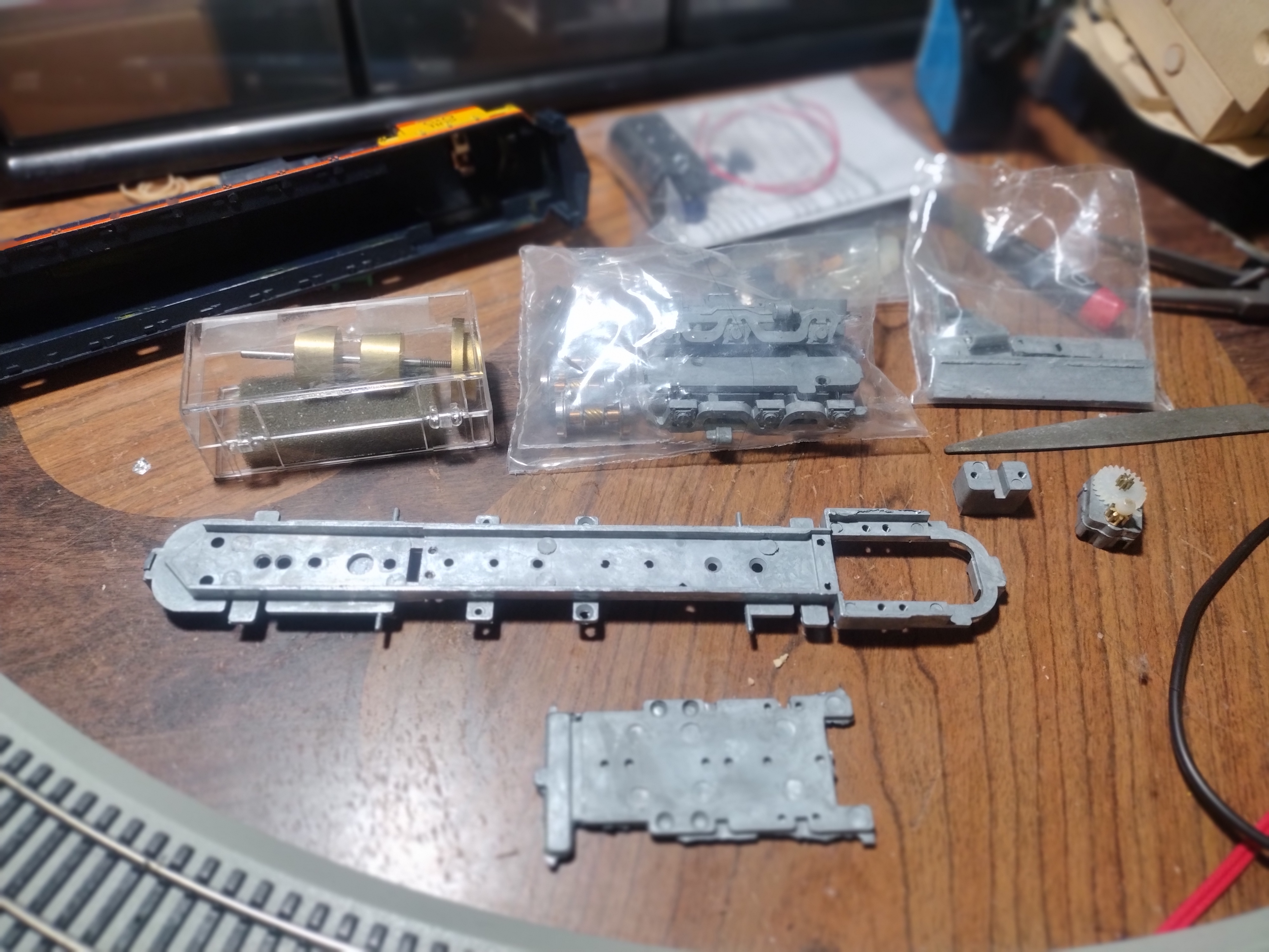
The contents of the kit. The locomotive frame and splice plate are at the bottom.
The unmodified frame fits in the Tyco shell perfectly, except for the length. This illustrates the difference between the SD45 and C630, and why the splice plate is necessary.
|
Country:  USA ~
Posts: 621 ~
Member Since: December 22 2013 ~
Last Visit: June 25 2026 USA ~
Posts: 621 ~
Member Since: December 22 2013 ~
Last Visit: June 25 2026
|
 Alert Moderator
|
|
|
|
Posted - May 23 2024 : 06:51:59 AM
|
SO here is the progress I"ve made so far on this project.
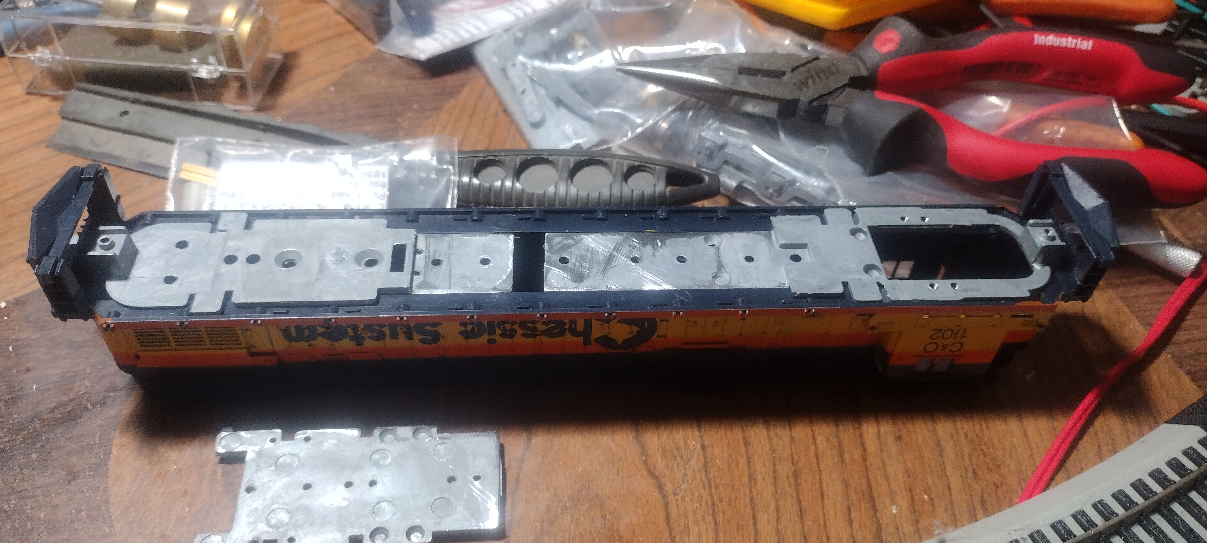
The frame has been cut in half, and test fitted to the shell. When completed, The frame will be secured to the shell by the couplers through the front and rear pilots. This is similar to the newer Atlas units.
Adding the splice plate showed two things. The frame spliced to fit the U28C using the pre-drilled holes in the frame and splice plate is still too short. DO I continue to build the kit as designed? This would require the use of long shank couplers, which might not be a bad thing considering this will run on 18" radius curves. DO I further extend the frame to fit and drill and tap my own holes? This would give the correct length. I have reached out to the manufacturer for advice.
The other issue is a minor one. The splice plate interferes with the bumps in the shell that hold the handrail stanchions. Notching the plate to clear these bumps will being the notches perilously close to the holes for the screws that hold the fuel tank on. I may just shave off the bumps for the stanchion holes, and hope for the best.
Originally posted by jward - May 23 2024 : 06:43:40 AM
|
|
Country: USA ~
Posts: 621 ~
Member Since: December 22 2013 ~
Last Visit: June 25 2026
|
Alert Moderator

|
|
|
|
Posted - May 23 2024 : 11:26:13 AM
|
 
So, this is going to be an all-in upgrade. Very nice.
|
|
Country: USA ~
Posts: 11686 ~
Member Since: December 09 2013 ~
Last Visit: May 26 2026
|
Alert Moderator
|
|
|
|
Posted - May 23 2024 : 3:09:29 PM

|
A fascinating build. Keep us updated!
Edited by - DaCheez on May 23 2024 3:09:41 PM
|
Country:  Canada ~
Posts: 3448 ~
Member Since: September 22 2006 ~
Last Visit: April 03 2026 Canada ~
Posts: 3448 ~
Member Since: September 22 2006 ~
Last Visit: April 03 2026
|
Alert Moderator
|
|
|
|
Posted - July 25 2024 : 10:16:56 PM
|
I have been working on this rebuild off and on over the past two months as I get the time and energy to do so. Building the kit is relatively straightforward, but you need to do cleanup on the castings. The more time and care you take with them the better your results will be. Here is a step by step of what I've done so far. I must say, this is probably the best engineered kit I've ever worked on. Tolerances are tight on many of the components and they fit together well without the play you normally find in even the better made locomotives.
After some thought I decided to build the kit as designed because it is the first one. I'll live with the odd truck spacing of the shorter frame for now. The important thing is to get this thing built and become familiar with the process. Modifications to the original design can be made on later kits.

Here is the splice to lengthen the frame. Note the odd screw. I couldn't find my 2-56 drill and tap set to drill out the hole for this screw, so I found one that fit from my stash of Bachmann parts. It fit the existing hole, and holds well. Notice the tabs on the original frame have been removed. They were for mounting the fuel tanks to an unstretched chassis.

Here is the fuel tank casting . There is one for each side of the chassis. Note the locating pins at either end of the casting, and the screw hole in the center. This is how the casting is mounted. The original Tyco fuel tank will eventually be epoxied to this casting.

The fuel tank attatched to the chassis. Note the locating pin fits in a hole in the chassis, and the tank is screwed to the chassis.

Here is the chassis with the two pillow blocks that will support the flywheels.


The pillow blocks are fastened to the chassis by screws underneath. The second photo shows them in position, as well as the bolster for the front truck. This completes the initial chassis assembly.
|
|
Country: USA ~
Posts: 621 ~
Member Since: December 22 2013 ~
Last Visit: June 25 2026
|
Alert Moderator
|
|
|
|
Posted - July 31 2024 : 3:06:18 PM
|
Next step is the trucks, which are accurate for most real C630s. As with most things in this kit they are unpainted cast metal. The two trucks are identical and go together exactly the same. The only difference between the two is the big gear on one of the worms. This one will be the front truck.

Here are all the parts. The casting has been cleaned up to remove flash. The worm rears come already mounted on their shaft but you have to add the spacer washers, bronze bearings and socket to the worm shafts. There are quite a few of the thin washers included in the kit, but you only use enough to take the play out of the worm gears in the trucks. The bushings have a lip on three sides but are flat on the remaining side. When you fit the worm into the slot in the truck, make sure those flat sides face up. The worms should fully seat in the slots and turn freely when you are done. You'll want to oil these bearings before they go into the trucks.

The wheelsets have a metal axle and one insulated hub. It is vitally important that when you assemble the truck all the insulated hubs are on the same side. Otherwise the whole truck shorts out. Whatever side you put the insulated hubs on, do the same with both trucks. When fully assembled they will face in opposite directions which will give you a positive and a negative truck. They also have their own bearings on the axles. Oil those then press fit them into the trucks. They should fully seat against the worms.

This is what the assembled truck looks like before the bottom cover is screwed on. Fully assembled you should be able to easily turn the wheels by rotating the socket coupling on the end of the worm.


The front and rear trucks shown fully assembled. In the third photo the chassis is in the background to show the proper orientation of the trucks.

The universal shaft is assembled with the red ball on one end. It is a press fit. The brass rod is cut to length. I started with 2 1/4" and trimmed it until the trucks swivelled independently of each other. The final length is around 2 1/8" the white ball slides on the shaft so it was easy to remove it to make these adjustments. Note the splines on the balls are 90 degrees offset from each other. Also shown is the underside of the fully assembled front truck.

Here is the universal in its final position.


The rear truck bolter gets a metal bushing in the hole. This one will be the same polarity as the frame.
The truck is secured through the bolster by a screw. The screw supplied in the kit was too short for my taste so I substituted a slightly longer one. Whatever length screw used must not be too long or it interferes with the turning of the worm.

The front truck will be insulated from the frame by plastic bushings and a longer screw. Note the metal bushing used on the rear truck.

One of the plastic bushings is inserted into the underside of the front bolster, then the chassis is flipped right side up. The other bushing fits on top of the bolster, and the long screw secures the truck to the chassis. It is at this point that I ran into a problem with shorting. You'll notice this kit is being assembled on my test track of 18" radius EZ track. I dm doing this because this locomotive needs to operate reliably on 18" radius. Upon assembly of the chassis I discovered the front truck was touching the chassis on this curve. Everything had to come apart for modifications.

On the chassis, I filed away part of the inner frame. The front bolster was also flipped around so the round nub faces the rear.

The front end of the front truck was also modified with a bevel. So far these modifications have solved the problem and the truck no longer shorts.

The final step of truck assembly is to add the gear tower to the front truck. It consists of a metal housing with bearings, a shoulder gear, and a gear with a ball coupling.

The sides of the gear tower were bevelled like the truck frame to prevent shorting.

The assembled gear tower should look like this. The shoulder gear goes on the bottom, and the ball gear on top.

The gear tower is secured to the truck with a pair of long screws. It should be oiled and greased before final assembly.


The final two photos show what the chassis looks like at this point. This completes the running gear. All that is left now is the motor and flywheel to complete the chassis.
Edited by - jward on July 31 2024 3:10:32 PM
|
|
Country: USA ~
Posts: 621 ~
Member Since: December 22 2013 ~
Last Visit: June 25 2026
|
Alert Moderator
|
|
|
|
 Posted - July 31 2024 : 4:13:25 PM Posted - July 31 2024 : 4:13:25 PM
|
Very nice project. Thanks for sharing this with us.
|
|
Country: USA ~
Posts: 7763 ~
Member Since: February 12 2014 ~
Last Visit: June 26 2026
|
Alert Moderator
|
|
|
|
Posted - July 31 2024 : 6:52:54 PM
|
That's a pretty good look at how this chassis goes together. Thanks.
Somewhere, I had the impression that on a 3-axle Hobbytown truck the center axle was an idler. This with all axles driven looks like a much better arrangement, especially if you have grade changes that could hump up in the middle of the truck.
Carpe Manana!
|
|
Country: USA ~
Posts: 2417 ~
Member Since: September 17 2013 ~
Last Visit: June 24 2026
|
Alert Moderator
|
|
|
|
Posted - August 02 2024 : 11:12:36 AM
|
This is something that people like you and me, with heavy grades on our layouts, can appreciate. They make a complete kit for an Alco RSD5 which should have a metal body and pull well. SInce I am partial to Alcos, I will be getting one and putting it up against the Atlas ones I already have.
|
|
Country: USA ~
Posts: 621 ~
Member Since: December 22 2013 ~
Last Visit: June 25 2026
|
Alert Moderator
|
|
|
|
Posted - August 03 2024 : 10:55:36 PM
|
Nice work on the loco and the very descriptive text/photos.
I went to the Hobbytown Boston site and it is really good. One item I found that may be of interest to other folks on this board is making exact weights for cars/engines. Per the website:
Bearmetal-158 is a low melting point eutectic alloy with about the same weight as pure
lead, but melts at about 158 degrees Fahrenheit. It can be used for a variety of model
railroading applications such as weighting locomotives and rolling stock as well as
casting detail parts. Bearmetal can be poured directly into plastic loco shells filling
cavities and voids completely, although care must be taken not to heat the metal any
higher than it takes to liquefy it. Bearmetal can be melted in a small vessel over a stove
or hot plate. It can even be melted in a cooking pouch in boiling water. Easy to work with
Bearmetal can be re-melted any number of times with little effect on the alloy properties.
The product comes with full instructions, tips for use and safety guidelines.
|
|
Country: USA ~
Posts: 553 ~
Member Since: February 18 2013 ~
Last Visit: January 01 2026
|
Alert Moderator
|
|
|
|
Posted - August 04 2024 : 2:20:06 PM
|
| Did you also see the Varney Aerotrain bodies, and the drive kit for them? You could probably assemble the entire train for about $150.
|
|
Country: USA ~
Posts: 621 ~
Member Since: December 22 2013 ~
Last Visit: June 25 2026
|
Alert Moderator
|
|