|
|
 Posted - March 15 2016 : 6:29:33 PM Posted - March 15 2016 : 6:29:33 PM


|
I was wondering if there is a way to make my own point-to-point reversing unit
for a Tyco trolley without having a degree in electrical engineering. The ready-to-go
Bachmann units are retailing on Fleabay for $135. Nooooope.
|
Country:  USA ~
Posts: 11686 ~
Member Since: December 09 2013 ~
Last Visit: May 26 2026 USA ~
Posts: 11686 ~
Member Since: December 09 2013 ~
Last Visit: May 26 2026
|
 Alert Moderator
|
|
|
|
Posted - March 15 2016 : 8:54:10 PM
|
| You might try using a couple of pressure switches and a relay to switch the track polarity.
|
|
Country: USA ~
Posts: 865 ~
Member Since: September 23 2014 ~
Last Visit: May 01 2023
|
Alert Moderator

|
|
|
|
Posted - March 16 2016 : 12:12:36 PM
|
An old Lionel 2-position E-unit reverser and a couple of pushbutton switches attached to bumpers should do it.
Wire both switches to the E-unit's coil, and wire the contacts to track power. Every time the trolley hits a bumper, it will pulse the E-unit and reverse the direction.
EDIT: On second thought, this won't work without an additional relay. The reason is, the 2-position reversers are SPDT switches, not DPDT like the 3-position. You can still use an E-unit, but will need to connect its common terminal, and one of the switched terminals, to a DPDT relay, and use that to reverse direction when it's energized.
This leaves the Snap Relay method, below, as probably the cheapest and simplest.
Edited by - Autobus Prime on March 17 2016 12:08:36 PM
|
|
Country: USA ~
Posts: 432 ~
Member Since: March 04 2008 ~
Last Visit: December 28 2018
|
Alert Moderator
|
|
|
|
Posted - March 17 2016 : 12:16:17 AM
|
| Sounds helpful, I'll look into it. Thanks.
|
|
Country: USA ~
Posts: 11686 ~
Member Since: December 09 2013 ~
Last Visit: May 26 2026
|
Alert Moderator
|
|
|
|
Posted - March 17 2016 : 07:57:43 AM

|
https://www.reddit.com/r/modeltrains/comments/4amnb5/dcc_adjustable_timed_reverse_delay/
There's a discussion on the matter on Reddit at the moment. One of the comments describes a DC version using two relays, some diodes, and a timer. It took me a few minutes to understand but it seems simple enough.
|
Country:  Canada ~
Posts: 3448 ~
Member Since: September 22 2006 ~
Last Visit: April 03 2026 Canada ~
Posts: 3448 ~
Member Since: September 22 2006 ~
Last Visit: April 03 2026
|
Alert Moderator
|
|
|
|
Posted - March 17 2016 : 09:37:33 AM
|
quote:
That circuit isn't going to work (http://imgur.com/XV6GU8n). With the relay as shown, the diode at left is basically short-circuiting the track. With the relay switched over, the diode at right short-circuits the track. The track will only see about ~0.7 volts in each position, the same as 1 diode's forward voltage drop.
If they used the timed relay to switch a DPDT relay that controlled the track power, the circuit would work, just shuttling the car back and forth with a time delay between each reversal. The longer the time delay, the longer the time between reversals.
|
|
Country: USA ~
Posts: 432 ~
Member Since: March 04 2008 ~
Last Visit: December 28 2018
|
Alert Moderator
|
|
|
|
Posted - March 17 2016 : 10:03:06 AM
|
Here is another way you could do it with an Atlas Snap Relay.
The Snap Relay simplifies things because it is a sort of latching relay, holding its position even after the coil is de-energized. Use it with a pair of normally-opened momentary pushbuttons, or perhaps some Trigor Track sections if you can find 'em.
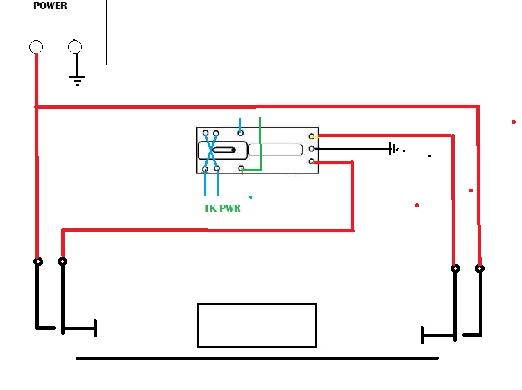
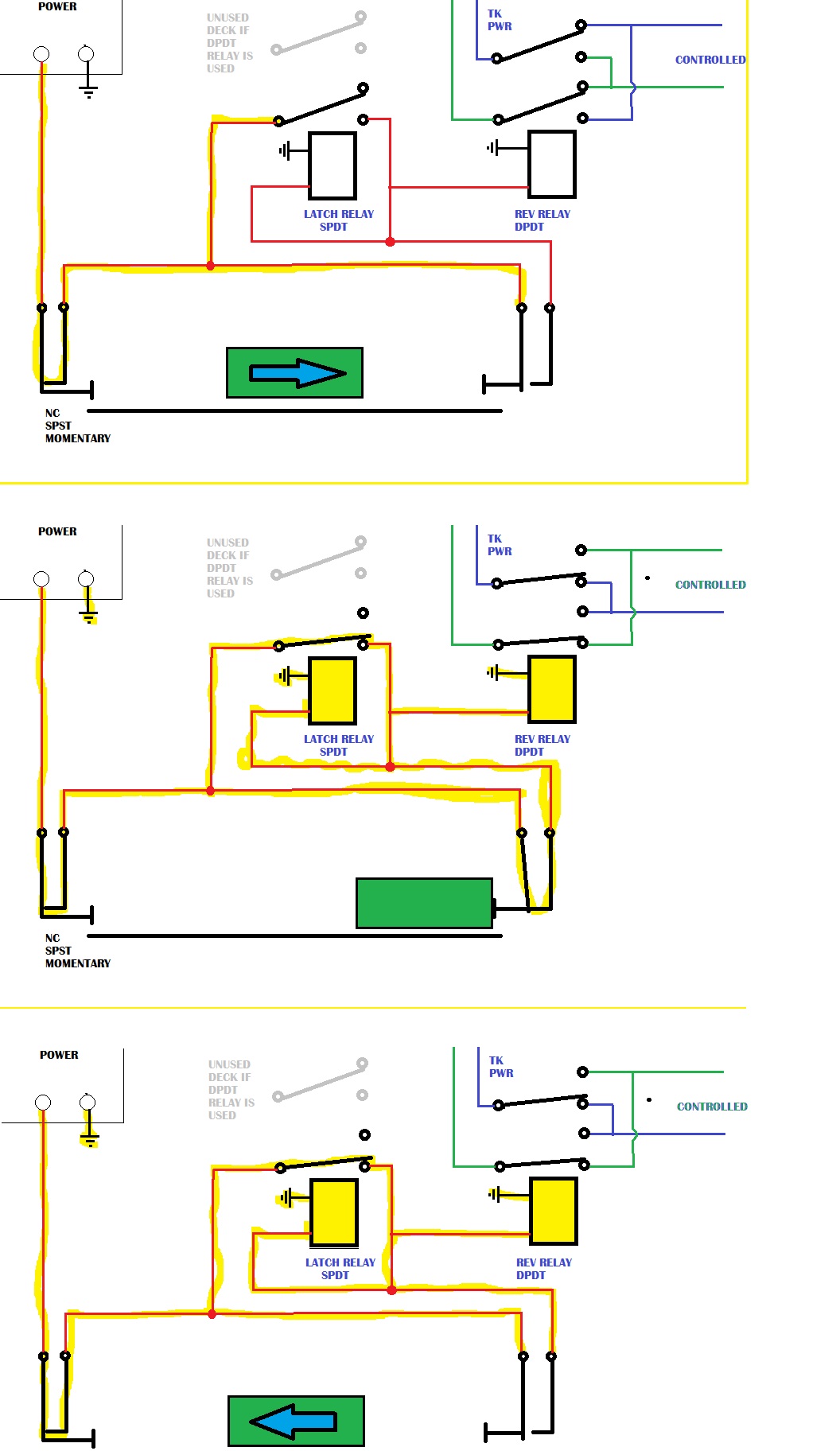
And here is another way you could do it with two ordinary relays. This requires maybe a bit more 'splainin so I added a few images and some cracklin' energy on the wires. If your wires are actually cracklin' with energy they you may wish to stop operating your trains in the kilovolt ranges.
In the design below, the SPDT relay (or a DPDT etc. with unused decks) acts as a latching relay by feeding back power through its own coil when switched-on. This holds the second DPDT relay in the 'reversed' position. This also means that the circuit will use a small amount of power continuously when the train is in 'reverse'. Snap Relays arent robust enough for this kind of continuously energized service (and they mechanically latch anyway) but you can get cheap multipacks of robust automotive relays on Amazon or Ebay that will do the job well at low cost.
Here is how it works. The car starts out going 'right' with neither relay energized. It hits the NO pushbutton and energizes the SPDT relay, which closes, energizing itself and the DPDT relay together. The DPDT relay reverses the track power,and the car goes left until it hits the NC pushbutton, opening its contacts, and removing power from the relays, which both open. Repeat cycle.
If you use that timed SPDT relay for the SPDT one here, you will get a delay at each end.
Edited by - Autobus Prime on March 17 2016 10:32:55 AM
|
|
Country: USA ~
Posts: 432 ~
Member Since: March 04 2008 ~
Last Visit: December 28 2018
|
Alert Moderator
|
|
|
|
Posted - March 17 2016 : 11:16:29 AM
|
The picture I was looking at was a little higher up in the thread, but it looks like that's a moot point. You seem to have nailed some good options here. I'll have to save this for later.
|
|
Country: Canada ~
Posts: 3448 ~
Member Since: September 22 2006 ~
Last Visit: April 03 2026
|
Alert Moderator
|
|
|
|
Posted - March 21 2016 : 5:08:04 PM
|
This looks almost doable for a complete know-nothing,
Now, the little gate thingy above the "latch relay SPDT",
is that a separate unit, or does the schematic simply
imply this a part of said "latch relay?"
The little black dots with the white centers, those are
merely terminal ends to connect unto?
I could find this stuff on line, I presume?
|
|
Country: USA ~
Posts: 11686 ~
Member Since: December 09 2013 ~
Last Visit: May 26 2026
|
Alert Moderator
|
|
|
|
Posted - March 21 2016 : 5:23:57 PM
|
quote:This looks almost doable for a complete know-nothing,
Now, the little gate thingy above the "latch relay SPDT",
is that a separate unit, or does the schematic simply
imply this a part of said "latch relay?"
The little black dots with the white centers, those are
merely terminal ends to connect unto?
I could find this stuff on line, I presume?
Originally posted by Chops124 - March 21 2016 : 5:08:04 PM
|
Yeah that whole big pile of stuff is one relay. The top switch-looking lines represent the relay contacts that get pulled from one position to the other when the coil (represented by the bit at the bottom) is engaged.
The Snap Relay is definitely the easiest way though, you don't even need the electrical latching.
|
|
Country: USA ~
Posts: 432 ~
Member Since: March 04 2008 ~
Last Visit: December 28 2018
|
Alert Moderator
|
|