|
|
 Posted - December 30 2014 : 12:35:05 AM Posted - December 30 2014 : 12:35:05 AM


|
Tycomaniacs:
September 1938. You want an HO loco, but the budget isn't there for a $22 Mantua Atlantic, or even one of the $12 Gilbert 4-6-4s that are currently making a big splash (ready-to-run, and half the price of the Mantua kit!) What do you do?
What else? You buy a Tyco and kitbash it.
...only it's 1938, remember. Tyco doesn't exist yet! That's years away. But Markllin does...and what Marklin is, is what Tyco would later be. RTR equipment of various scale fidelity, sold at a low price for the toy market. In Germany. Disregarding for the moment certain political situations in Germany (!) ... a basic O gauge Marklin set sold there for the equivalent of four 1938 U.S. dollars. Keeping in mind that import duties on toys would nearly double this price (at that time), H.O. Williams was still able to get a small Marklin loco to modify for about 5 or 6 dollars (if my calculation is correct). Model railroaders in 1938 spent an average of $2 per week on their hobby (according to a MR poll taken about that time) so this didnt' seem so bad at all...
So that is what he did. And here is what he made.
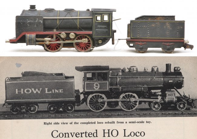
Not bad! And using several clever tricks I'll write up in more detail tomorrow, tricks we could easily use now. But I would advise against starting with the same Marklin engine. It's the Marklin R-700. A cheap loco at the time, I just saw one on Ebay...for $3,900!!! (Edit: OK, 2900. But still!)
But you could almost follow this procedure with a Model Power shifter. Right?
Here's the drawing he made of the kitbash, which I'm including to show how scale drawings were usually presented in those days...
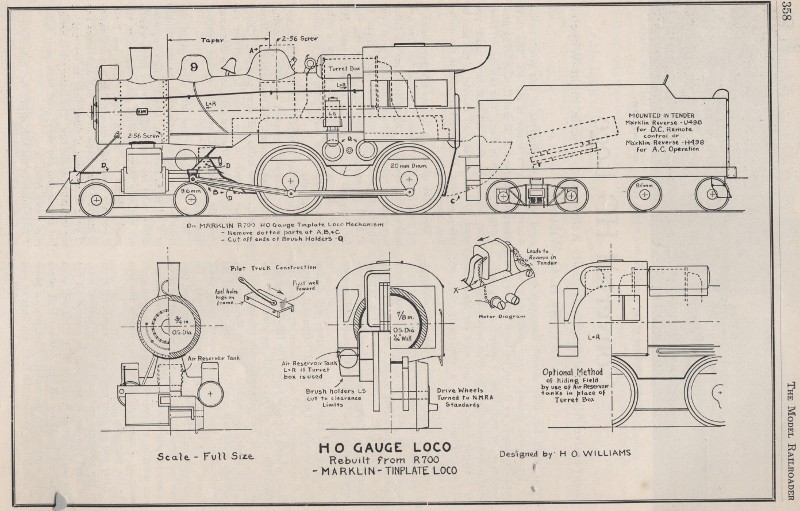
Simple and semi-schematic yet serviceable and easy to read. Very much like a railroad shop drawing.
More details to come, stay tuned...
Edited by - Autobus Prime on December 30 2014 3:07:39 PM
|
Country:  USA ~
Posts: 432 ~
Member Since: March 04 2008 ~
Last Visit: December 28 2018 USA ~
Posts: 432 ~
Member Since: March 04 2008 ~
Last Visit: December 28 2018
|
 Alert Moderator
|
|
|
|
 Posted - December 30 2014 : 12:59:06 AM Posted - December 30 2014 : 12:59:06 AM
|
| That is quite a find Autobus, and some neat information. It is interesting to peg down years of production and other details. And, that drawing! Crazy. Where did you find this stuff (if I might dare ask)?
|
|
Country: USA ~
Posts: 2087 ~
Member Since: March 16 2013 ~
Last Visit: July 05 2018
|
Alert Moderator

|
|
|
|
Posted - December 30 2014 : 01:11:59 AM
|
Very interesting piece of kitbashing history, I must say. It's so good that it's hard to tell that the kitbash actually came from the Marklin. It's so good that it's hard to tell that the kitbash actually came from the Marklin. 
-Steve
"A lot of modellers out there who go to these train shows see broken HO stuff and go, 'This is useless' when, in reality, they can still be used for modeling whether it's as a prop on your layout or a cool project to make something old new again."
|
|
Country: USA ~
Posts: 3533 ~
Member Since: February 17 2014 ~
Last Visit: January 11 2023
|
Alert Moderator
|
|
|
|
Posted - December 30 2014 : 10:27:25 AM
|
course I wouldn't be surprized if that Marklin is a rare collectable today! 
|
|
Country: USA ~
Posts: 15028 ~
Member Since: February 23 2009 ~
Last Visit: June 15 2026
|
Alert Moderator
|
|
|
|
Posted - December 30 2014 : 10:55:14 AM

|
AP,
Your post rekindled a idea I have had from time to time, would Bachmann's Thomas line have any useful kit bashing parts. Some of the engine's drive trains could be used as a tender drive or a small industrial locomotive. Maybe a drive for some older steam engines.
Regards, John
Mr. Rumson, in a community of 400 men, would you rather I took my bath "bare beam and buck naked" in the middle of the day? <> Elizabeth - Paint Your Wagon
|
|
Country: USA ~
Posts: 886 ~
Member Since: January 11 2012 ~
Last Visit: December 16 2023
|
Alert Moderator
|
|
|
|
Posted - December 30 2014 : 12:54:44 PM
|
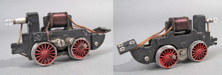
What a cool project, although something that I'm sure would make today's Marklin collector wince. I'm sure it scales to at least OO if not larger, given the size of the drive (a robust pancake motor drive, btw).
Are there any pictures of it under construction?
The Tyco Depot
|
|
Country: USA ~
Posts: 3927 ~
Member Since: June 20 2007 ~
Last Visit: November 19 2015
|
Alert Moderator
|
|
|
|
Posted - December 30 2014 : 3:06:18 PM
|
Buss, NKP: In-deed :D :
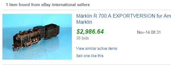
(The export version, with a cowcatcher, is evidently $ rare $. :) )
(Needless to say, I am NOT in the market for stuff of this type. :D )
Barry: September 1938 MR, page 357 (they numbered the whole year's pages in 1 series, back then) I've got the whole year plus some of 1939 and 1940, and there's a LOT of cool stuff in it that I eventually want to share here.
kovacs: Indeed, a lot of it isn't Marklin. The superstructure and tender are completely scratchbuilt, but in 1930s terms this is still a conversion...
JRG: I have one Thomas loco, Percy. He's small and very light, but anything can be a basis for a kitbash. I don't know anything about the larger Thomas locos.
NKP:
The original seems taller, but if the drivers are 20mm as claimed, that's about 69", and the cab roof is a bit over 14 feet from the railhead. It's a burly, high-boilered, modern American, and it's wrapped pretty tightly around that bulky motor, but it seems reasonably close to HO. The lagged steam turret by the cab, needed to clear the motor field, is pretty much an anachronism. Might as well add some smoke lifters and a Mars light, but compromise is the game when you're kitbashing. ^_^
No progress shots available, it wasn't done like that in those days of MR. Lead photo, drawing, one small photo showing the complete loco next to the removed Marklin superstructure and tender, and three pages of densely informative text.
I did dig up some internet photos of the R-700 mechanism, however. As you said, robust. :)
Edited by - Autobus Prime on December 30 2014 3:52:31 PM
|
|
Country: USA ~
Posts: 432 ~
Member Since: March 04 2008 ~
Last Visit: December 28 2018
|
Alert Moderator
|
|
|
|
 Posted - December 30 2014 : 8:25:32 PM Posted - December 30 2014 : 8:25:32 PM
|
| SEE?? I knew it!
|
|
Country: USA ~
Posts: 15028 ~
Member Since: February 23 2009 ~
Last Visit: June 15 2026
|
Alert Moderator
|
|
|
|
Posted - December 31 2014 : 09:16:59 AM
|
Citizens of Tycotown:
Okay, now here is how Williams did it.
*
To begin, he removed the entire R-700 superstructure, including the main rods and cylinder assemblies, trimmed down the R-700 mechanism where shown by the dashed lines, turned down the wheels to NMRA standards, and insulated it for two-rail.
Points of interest:
-NMRA standards were continually referred to. The NMRA was only three years old. The hobby and gauge were developing fast!
-The Marklin loco was 20 VAC three-rail, HO was 2-rail, 6 VDC.
Conversion was done by changing the series-wound motor to shunt-wound and adding a Marklin reversing rectifier (selenium button) in the tender. Williams recommended insulating wheels at the rim, but described insulating the wheels at the hub, which was easier with simple tools. Wheel was removed, drilled out, a fiber bar was pressed in, and drilled out, then trimmed. The wheel was reinstalled and quartered. No detailed description of quartering procedure. He noted that hub insulation would also require a fiber (insulating) main rod on the insulated side. He turned his own wheels to NMRA width and flange standards, but said that modelers without a lathe could get this job done at a local hobby shop. I wish my LHS had a lathe...
Eric LaNal, in a 1935 Model Craftsman article I also have, recommended taking wheels to a jeweler for similar work, saying it would cost probably $1 in1938USD. Real jewelers do sometimes have small machine tools, and this idea could still have potential. I've noticed that jewelers are often tinkerers by nature and not averse to taking on quirky projects, if you chat them up a bit.
I also note that the other article, by Eric LaNal, had more information about the Marklin loco, which was coyly referred to without trade names (trade names were 'taboo' in Model Craftsman). The R-700 had a US distributor, and my guess at pricing was correct - it sold for about six dollars. Saying it was a good-running loco, LaNal was put off somewhat by the perceived difficulties of converting a 3-rail 20VAC loco to 2-rail 6VDC...but as we can see, Williams saw no particular difficulty with it. Three years may have made a differenct (but more on that in a bit). I do have to wonder how the shunt winding affected its performance.
*
After the chassis mods, crank pins and side rods were added. The chassis was extended with brass bar. Cylinders, superstructure, pilot truck, and details were built up from brass and added to the chassis.
Points of interest:
-Williams noted that all parts had been turned or shaped from brass, but also noted that stacks, domes, cylinders, and other castings had become available since his loco was built. This shows how fast the hobby was developing. The R-700 wasn't available until 1935 ... and that was only three years before Williams' article. Those detail castings had all appeared within the previous three years or less!
-This note also suggests that the article was written quite some time after the loco was actually completed.
-The use of primarily brass is very different from Eric LaNal's HO loco articles, which relied on lots of wood, card, and tin. Williams' own much later Dollar Car articles, likewise, used a lot of wood and card. But not this one. The parts are metal and the emphasis is on solidity. The cylinder block is built up from brass and soldered in place on the frame. The boiler is made by tapering a piece of 7/8" brass tube to a feather edge and telescoping it over a piece of 3/4" brass tube. Piston rods and crosshead guides are 3/32 steel drill rod.
-Counterweights are added with hard sealing wax (No epoxy in 1938!) Crankpins are added to the blank drivers by filling in between two spokes with solder, then drilling and tapping a hole. Note that these rods carry no drive load; the Marklin loco has all wheels geared. Rods are not fluted; they are colored with a black stripe to give the impression of fluting.
-Rivet impressions are negative, created with a prick punch, as seen in recent (2000's) MR.
-Pilot truck is attached with a swinging arm pivoted as far back as possible, and over the forward axle of the truck itself. This seems rather conducive to tracking, and I may try it myself at some point, instead of pivoting in the center.
Pilot truck picks up power from the same side as the drivers
*
With the loco complete, a tender is built from sheet brass with a plywood floor, with the rectifier inside it. Trucks are purchased archbar type, arranged to pick up power from the opposite rail as the drivers and pilot truck. Loco is painted "with thin coats of paint" as needed, so as not to hide detail with a thick coat. The color used was a subdued gray-green, with some black detailing on the smokebox and elsewhere.
And that's the summary. I hope everyone enjoyed this trip into 1938. As previously seen, this loco had been in use for some time when the article was written, and Williams seemed quite pleased with it.
Edited by - Autobus Prime on December 31 2014 09:18:12 AM
|
|
Country: USA ~
Posts: 432 ~
Member Since: March 04 2008 ~
Last Visit: December 28 2018
|
Alert Moderator
|
|
|
|
Posted - December 31 2014 : 12:24:19 PM
|
quote: I hope everyone enjoyed this trip into 1938.....
Originally posted by Autobus Prime - December 31 2014 : 09:16:59 AM
|
Very much so AB, that was an absolutely fascinating write-up.
Hobbyists back in the day really had to know their stuff, didn't they?
http://tycodepot.com/
|
|
|
|
|
Posted - December 31 2014 : 12:50:11 PM
|
quote:
Hobbyists back in the day really had to know their stuff, didn't they?
Originally posted by JNXT 7707 - December 31 2014 : 12:24:19 PM
|
JNXT:
I think of it more as having incentive to learn. You could railroad at all skill levels, just like you can now, but there were rewards for gaining skills, and the hobby press made it their business to provide the opportunities.
Edited by - Autobus Prime on December 31 2014 1:06:51 PM
|
|
Country: USA ~
Posts: 432 ~
Member Since: March 04 2008 ~
Last Visit: December 28 2018
|
Alert Moderator
|
|
|
|
Posted - December 31 2014 : 1:55:57 PM
|
quote:Saying it was a good-running loco, LaNal was put off somewhat by the perceived difficulties of converting a 3-rail 20VAC loco to 2-rail 6VDC...but as we can see, Williams saw no particular difficulty with it. I do have to wonder how the shunt winding affected its performance.
Originally posted by Autobus Prime - December 31 2014 : 09:16:59 AM |
That is a fascinating question. Getting the field coil and the motor in parallel rather than in series would help with the change from 20 to 6 volts. At least, they wouldn't be dividing the voltage (of which there is now so little) between the two.
The selenium diodes make the field coil much like the permanent magnet in a DC motor. For the coil to be energized regardless of direction would need a bridge rectifier, meaning the coil is in series with two selenium diodes at any given time. What little I could find about the voltage drop across selenium rectifiers gives a 1 volt per diode drop as a rule of thumb, so starting with 6vdc, you end up with the coil at only 4 volts when the armature has 6 and close to 0 volts when the armature has 2.
Apparently, all motion takes place within a 4 volt window. I'd guess that the performance might have been better than nothing, but not what you'd have in a post-war model with real DC motors.
Carpe Manana!
|
|
Country: USA ~
Posts: 2417 ~
Member Since: September 17 2013 ~
Last Visit: June 16 2026
|
Alert Moderator
|
|
|
|
Posted - January 02 2015 : 10:58:21 AM
|
quote:
The selenium diodes make the field coil much like the permanent magnet in a DC motor. For the coil to be energized regardless of direction would need a bridge rectifier, meaning the coil is in series with two selenium diodes at any given time. What little I could find about the voltage drop across selenium rectifiers gives a 1 volt per diode drop as a rule of thumb, so starting with 6vdc, you end up with the coil at only 4 volts when the armature has 6 and close to 0 volts when the armature has 2.
Apparently, all motion takes place within a 4 volt window. I'd guess that the performance might have been better than nothing, but not what you'd have in a post-war model with real DC motors.
Originally posted by scsshaggy - December 31 2014 : 1:55:57 PM
|
scs:
In this case, only 1 diode per direction - Marklins have a center-tapped field winding that uses one side for each direction. The AC reverser is a SPDT relay, and the DC rectifier is 2 diodes.
Modern Marklin wiring diagram. With German names for model train parts. Old Marklin will be similar, but without the capacitors (you can see the three-terminal field connector on the motor image above):
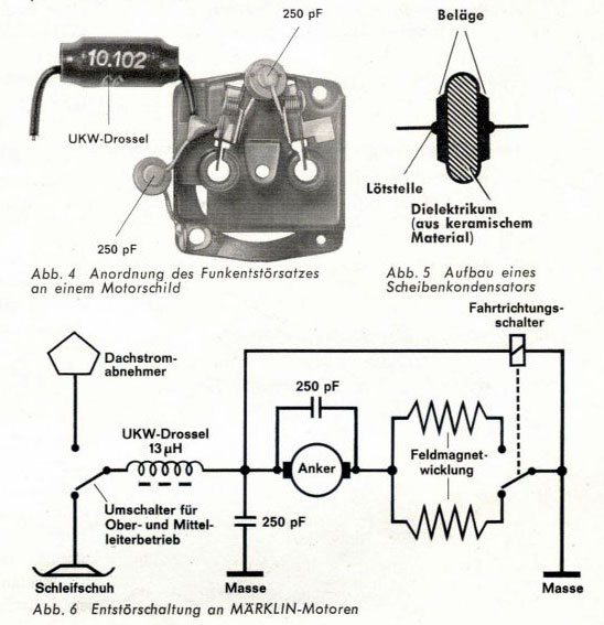
So 5 volts max, but still (as modified by H.O. Williams) a shunt winding which puzzles me. Shunt DC motors tend to have high torque but an almost constant speed. Did this loco have any speed control at all? Maybe the spur gearing compensated for this somewhat and kept the loco from starting with a sudden jerk.
Edited by - Autobus Prime on January 02 2015 4:12:38 PM
|
|
Country: USA ~
Posts: 432 ~
Member Since: March 04 2008 ~
Last Visit: December 28 2018
|
Alert Moderator
|
|
|
|
Posted - January 02 2015 : 6:05:47 PM
|
I read a description of how the speed is constant and it read as if the speed is constant regardless of load:
https://www.wisc-online.com/learn/career-clusters/stem/iau13708/the-dc-shunt-motor
Reading this, it also seemed like a permanent magnet motor would have the same properties.
Is the shunt-wired DC motor also constant regardless of voltage?
Carpe Manana!
|
|
Country: USA ~
Posts: 2417 ~
Member Since: September 17 2013 ~
Last Visit: June 16 2026
|
Alert Moderator
|
|
|
|
Posted - January 02 2015 : 8:27:41 PM
|
I can see where he would have to switch to a parallel arrangement given that the voltage was less than half, but I wasn't aware of how the field and armature tend to equalize each other. Was there any mention of how it performed? (What, no video? )
The Tyco Depot
|
|
Country: USA ~
Posts: 3927 ~
Member Since: June 20 2007 ~
Last Visit: November 19 2015
|
Alert Moderator
|
|
|
|
Posted - January 03 2015 : 2:56:24 PM
|
quote:
A permag motor's field flux is independent of the supply current, though. A shunt wound motor's field strength depends on the supply current as well as the back emf generated in the armature. So they interact more than they would with a permanent magnet.
Looking for Marklin specific info, I did find this over on the Model Train Journal forum:
quote:
Years ago when i made railroading in German prototype i had several Märklin H0 locos.
These have serial wound split field motors just as described in the postings before. The only significant difference to the Lionel motors, there are two wounds on the field coil. One wound left, the other one wound right. An over tension relay switches either to the left or the right wound. Thus creating the forward or reverse run of the motor. Similar just the same duty as an Lionel E-Unit do.
Several dozen of the Märklin stuff i converted to 2-Rail DC with their original Motors. The field wounds were still in series with the motor and simply steered by two diodes. Each for each field wound and so the motors were converted to DC and can go in reverse by changing the polarity of the DC current.
But how do they run?
Remember toy trains have only 3 speeds:
- fast
- faster
- still faster
Not so affordable when you try to run your train at prototypically speeds.
And this to DC converted serial field motors will still run at toy train speeds.
The real problems begin to show when the train is entering a grade, in this case an grade up. It slows down to a merely creeping and if the train is too heavy the engine even stalls at the given voltage. You have to throttle up to keep the train moving on.
The train comes now to the break even point.
Now it is go'in the grade down. It collects speed. More speed and going faster and faster.
You have to governor the train and turn the power knob down.
The end of the downgrade is reached an again the speed of the train changes significant.
Again you have to turn the throttle knob.
There is no satisfaction in the action.
I began to convert the motors to shunt wired ones. With an Graetz Brücke (full wave rectifier bridge) just like Wayne has shown in his diagramm.
In the case of the Märklin motors i had to rewound one of the two woundings in the other direction. So i have one wound in one direction.
The characters of these converted motors meet the needs of model railroaders much more.
The same stretch of rails as in the example above:
On the straight even track you turn the knob to increase voltage to set your desired speed.
The train is running at this speed, even in tight curves.
The grade begins. Train is still running in setted speed.
Break even point, then grade down. Train is still running in setted speed.
End of downgrade. Train is still running in setted speed.
The only time when you reach to the throttle knob is when you set the voltage initially.
A from series to shunt wound converted motor have an lower rpm level at all.
It will keep it's rpm more constant.
The rpm's will not so increase dramatically as an series wound motor when increasing the voltage.
And more torque at the same given voltage and current.
|
It sounds as if the changes this poster made for shunt winding did result in some speed regulation, if less than with series? It's still a bit of a puzzle what Williams did.
Source: http://www.modeltrainjournal.com/phpBB3/viewtopic.php?f=10&t=12136&start=15
quote:| I can see where he would have to switch to a parallel arrangement given that the voltage was less than half, but I wasn't aware of how the field and armature tend to equalize each other. Was there any mention of how it performed? (What, no video? ) |
I got yer video right here, bud.
That's the original Marklin running flat out on 20 VAC though. So it really doesn't answer the question. :D
Edited by - Autobus Prime on January 03 2015 3:19:57 PM
|
|
Country: USA ~
Posts: 432 ~
Member Since: March 04 2008 ~
Last Visit: December 28 2018
|
Alert Moderator
|
|
|
|
 Posted - January 03 2015 : 10:54:06 PM Posted - January 03 2015 : 10:54:06 PM
|
quote:
I got yer video right here, bud.
Originally posted by Autobus Prime - January 03 2015 : 2:56:24 PM
|
Wow. Those 1938 video cameras weren't half bad. Clearly before the invention of the Hoover, tho.
The Tyco Depot
|
|
Country: USA ~
Posts: 3927 ~
Member Since: June 20 2007 ~
Last Visit: November 19 2015
|
Alert Moderator
|
|
|
|
Posted - January 04 2015 : 07:56:40 AM
|
quote:Clearly before the invention of the Hoover, tho.
Originally posted by NickelPlate759 - January 03 2015 : 10:54:06 PM
|
Herbert or J. Edgar? I think they were around, then.
Carpe Manana!
|
|
Country: USA ~
Posts: 2417 ~
Member Since: September 17 2013 ~
Last Visit: June 16 2026
|
Alert Moderator
|
|
|
|
Posted - January 04 2015 : 1:45:52 PM
|
quote: quote:Clearly before the invention of the Hoover, tho.
Originally posted by NickelPlate759 - January 03 2015 : 10:54:06 PM
|
Herbert or J. Edgar? I think they were around, then.
Originally posted by scsshaggy - January 04 2015 : 07:56:40 AM
|
We can't see J. Edgar Hoover in the video, but that doesn't meant the FBI chief isn't stocking around somewhere off-camera.
|
|
Country: USA ~
Posts: 432 ~
Member Since: March 04 2008 ~
Last Visit: December 28 2018
|
Alert Moderator
|
|