|
|
 Posted - November 20 2013 : 8:03:04 PM Posted - November 20 2013 : 8:03:04 PM


|
If any of you follow MRH online (and I download each issue!), you may have seen the motorized Athearn 200 ton crane built by DR. Geoff Bunza. While this is quite an achievement, I ONLY want to add some LED lights to my second model of this crane, both one in the back and two in the front, similar to what he did.
Here is where I get into the weeds. I know how to wire two LEDs so that one lights when an engine reverses and the other end lights when it is going forward- very simple reversal of the positive and negative leads (with accompanying appropriate resistors, of course) for the rear LED.
I saw a diagram of a constant lighting circuit that would allow all lights to remain on when powered: 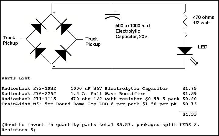
I need to figure how to wire in three LEDs on one circuit in this instance.
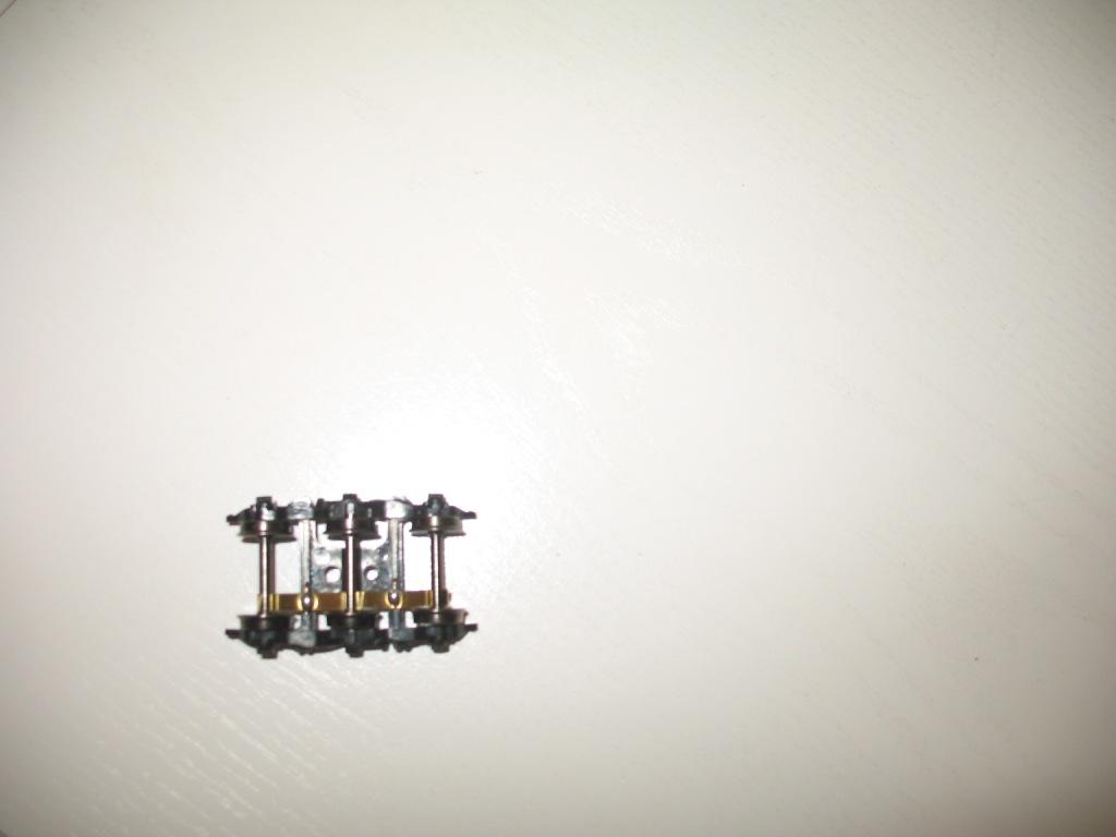
I improved on the good doctor's wipers in this manner (two trucks with IM wheels, with the wiper on the uninsulated side), using a .025 phosphor bronze wire thru a small hole in the truck crossbar, then soldered to the wiper as it lays across the wiper. The other portion of the wire is bent at the other end of the crossbar thru hole in a S shape to keep it in place w/o adhesives:
Before I start adding the power wire to each truck, I want a clear idea of what I am doing.
I want to bring the truck power wires up into the cabin floor (and have already drilled a hole in the round "turret" to do so) and solder them to two separate small brass pieces (left and right feeds from each truck) attached to the rear floor of the cabin. Then I want to attach the circuit properly to each brass piece so that the LEDs remain light whether the crane is moving forward or backward.
I don't really know how to do things properly, other than I decided that 2-wire female and male mini-connectors should be running from the LEDs into the circuit to make removal of the cab shell easy. Do I wire the LEDs in parallel or in series, etc.
Another issue is whether to use 470 ohm resistors or 1000 ohm resistors in this circuit.
I will be using 3mm flat LEDs.
Any assistance from a knowledgeable forum member will be greatfully appreciated. PM me if it will be easier to have a conversation, or reply here....
Thanks.
Siouxlake Ron
|
Country:  USA ~
Posts: 510 ~
Member Since: September 21 2011 ~
Last Visit: December 21 2014 USA ~
Posts: 510 ~
Member Since: September 21 2011 ~
Last Visit: December 21 2014
|
 Alert Moderator
|
|
|
|
Posted - November 21 2013 : 11:18:15 AM

|
Ron,
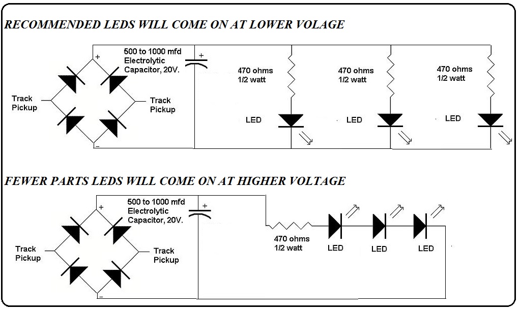
I think one of these circuits will do the trick. I would wire the circuit and test the results before I put it in a car.
NOTE:
OOPS! I'm Sorry I did not read your post very carefully. The circuit you provided and the ones I supplied are not constant lighting for DC operation. They may work for DCC. In DC operation they will vary with the amount of voltage supplied to the track. I have not built a constant circuit for just car lighting, and will not recommend a circuit I have not used. This circuit should minimize the light flicker, but is not a constant brightness circuit.
Regards, John ****************************************************
I told him, 'Son, what is it with you. Is it ignorance or apathy?' He said, 'Coach, I don't know and I don't care. <> Frank Layden
Edited by - JRG1951 on November 21 2013 3:09:56 PM
|
|
Country: USA ~
Posts: 886 ~
Member Since: January 11 2012 ~
Last Visit: December 16 2023
|
Alert Moderator

|
|
|
|
Posted - November 21 2013 : 11:20:36 AM
|
never heard of MRH online....what is the link??
just me Ray... and just because I have Tyco doesn't mean I am not a model railroader
|
|
Country: USA ~
Posts: 506 ~
Member Since: April 03 2011 ~
Last Visit: November 29 2025
|
Alert Moderator
|
|
|
|
Posted - November 21 2013 : 11:31:28 AM
|
Great online publication, their forum is great too, but many rivet counters.
http://model-railroad-hobbyist.com/
Regards, John **************
Don't pick a fight with an old man. If he is too old to fight, he'll just kill you. <> Clint Smith
Edited by - JRG1951 on November 21 2013 11:32:14 AM
|
|
Country: USA ~
Posts: 886 ~
Member Since: January 11 2012 ~
Last Visit: December 16 2023
|
Alert Moderator
|
|
|
|
Posted - November 21 2013 : 3:08:40 PM
|
Ron,
OOPS! I'm Sorry I did not read your post very carefully. The circuit you provided and the ones I supplied are not constant lighting for DC operation. They may work for DCC. In DC operation they will vary with the amount of voltage supplied to the track. I have not built a constant circuit for just car lighting, and will not recommend a circuit I have not used. This circuit should minimize the light flicker, but is not a constant brightness circuit.
Regards John *****************
Ineptocracy(in-ep-toc’-ra-cy) - a system of government where the
least capable to lead are elected by the least capable of producing,
and where the members of society least likely to sustain themselves
or succeed, are rewarded with goods and services paid for by the
confiscated wealth of a diminishing number of producers.
Edited by - JRG1951 on November 21 2013 3:11:24 PM
|
|
Country: USA ~
Posts: 886 ~
Member Since: January 11 2012 ~
Last Visit: December 16 2023
|
Alert Moderator
|
|
|
|
Posted - November 21 2013 : 6:48:58 PM
|
quote:This circuit should minimize the light flicker, but is not a constant brightness circuit.
Originally posted by JRG1951 - November 21 2013 : 3:08:40 PM
|
Neither is the circuit Ron posted, which is the same as the top diagram in yours minus 2 LED's. LED's have lass variation in brightness than incandescents, so that should do fine. 
The Tyco Depot
|
|
Country: USA ~
Posts: 3927 ~
Member Since: June 20 2007 ~
Last Visit: November 19 2015
|
Alert Moderator
|
|
|
|
Posted - November 21 2013 : 11:04:11 PM

|
First rule is you should ALWAYS wire the LEDs in parallel, with each having it's own resistor - the reason is, if you do so in series, the weakest LED won't be as bright as the others. You can wire them in series for 2 or 3 of them, but it's not recommended practice. Better to have each have their own resistance.
The diodes are also a voltage/current limiting device, so you won't overdrive them with 12-16 volts, as they are 3.3 volt devices for the most part. If you have multiple LEDs, you can get what is called a RESNET - it's a yellow rectangular multi-resistor pack, you can get them as single voltage input / multi-output, or multiple inpvt-output configuration, that way you only need one for 4 or 5 resistors at a time.
The 4 diodes in the circuit provide the two-way inputs to allow lighting no matter which direction you are in. The large cap I think is to buffer the voltage to the LEDs, like a battery. That prevents the flickering.
Jerry
" When life throws you bananas...it's easy to slip up"
|
|
Country: USA ~
Posts: 3974 ~
Member Since: January 04 2009 ~
Last Visit: January 11 2019
|
Alert Moderator
|
|
|
|
Posted - November 22 2013 : 12:15:25 PM
|
What's trhe best gauge of wiring for accessories & track? 
|
|
Country: USA ~
Posts: 15028 ~
Member Since: February 23 2009 ~
Last Visit: June 15 2026
|
Alert Moderator
|
|
|
|
Posted - November 22 2013 : 6:08:48 PM
|
John/JRG1951:
I will take your top schematic and Nelson's sage advice as my blueprint. The idea to make a benchtop test circuit is a good one, now that I am starting to get into more complex lighting projects, so I can get back to some cabooses and those Athearn RDCs and light them better (as well as in the first place).
About Model Railroad Hobbyist:
To those that have reservations about MR (although I found a $29.98 promotional and re-upped after three years of retail (barnes & Noble) purchasing, Model Railroad Hobbyist is a very robust multi-gauge publication with extensively well- imaged articles. I download the "embedded" file each month, then transfer each year to a separate CD (or DVD now, as some monthly edition files have grown). It is a home-brewed version "a-building" of the MR 75 year digital offering, although I only have 09/10/11/12 and soon 2013 collected so far (09 was when they started with 4 quarterly issues). Lots of reading at your leisure, many relevant how-to articles and educational stuff. The speed at which they can compile and modify eacg monthly issue enables them to update product and news announcements to just before release/publication online, (instead of finding out in November that Athearn released a series of new cars last July, etc), as well as receive any corrections to articles or enhancements up to "press time".
Back to the schematic stuff:
I don't intend to become an electronics tech in order to do small circuits, as that is a hobby in itself. One thing that I should mention about my own electronics and LED adventures is that I evolved from buying a five-pack of 470 ohm resistors at Radio Shack and scrounging LEDs from after-Xmas LED strings to buying bulk of what I need- 3mm round and flat top warm whites, bulk 470 and 1K ohm resistors, as well as shrink tubing on Ebay, where a few dollars plus free shipping from China beats any prices at the Shack (like: $3.00 or so for 100 resistors and free shipping!). There is no one around at those stores to ask for help- they are only retail clerks, and most customers wouldn't know a soldering iron from a Proctor-Silex iron with a steam jet, not to mention that tiny area of electronics parts drawers in the very rear of their mall stores. For this project, I have everything but the capoacitor and the bridge diode, but will get them locally as one-offs for this project. If things work out well, Ebay will get my bulk business.
The Athearn Crane motorization (and, for me, lighting) project is very complex, but it represents the kind of stuff that takes us out to the frontiers of what can be done.
Thanks for the quick help, guys- I am off for the whole Turkey week as of tonight and will post some of my recent flea market acquisitions and recent projects this next week.
In the meantime, I wish all of you a Happy Thanksgiving- enjoy time with your families and friends!
Siouxlake/ Ron
|
|
Country: USA ~
Posts: 510 ~
Member Since: September 21 2011 ~
Last Visit: December 21 2014
|
Alert Moderator
|
|
|
|
Posted - November 22 2013 : 11:01:34 PM
|
Ben,
Your wiring gauge question is a bit general. In HO You can generally use 20 gauge or larger wire for most model circuits. On layouts the currents are generally low. The gauge factor is more a matter of length than current capacity. If you have very long runs, 25 feet or more you should use larger wire. This will prevent voltage loss.
On modern HO cars and loco wiring, wires as small as 26 gauge are OK. 22 gauge would be better on older models. I would not use solid wire in your mobile models. The more flexible is perfered in this application.
DCC wiring requires special consideration on larger layouts. Read more here.
http://www.amhobby.com/products/tech/generic/wire_sizes.html
Be sure and learn about the quarter test.
Hope this helps. John *******
Life is sexually transmitted. <> Unknown
|
|
Country: USA ~
Posts: 886 ~
Member Since: January 11 2012 ~
Last Visit: December 16 2023
|
Alert Moderator
|
|
|
|
Posted - November 29 2013 : 11:36:20 PM
|
Here is a location diagram I made for the Athearn 200 Ton Crane cab, where I am planning to install 3 LEDs, based on the prior responses with schematics relating to a constant lighting circuit:
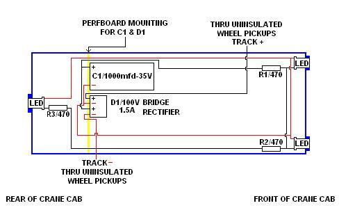
I found a 35V/1000mfd capacitor and a 100V/ 1.5A bridge rectifier diode at Radio Shack and will use either spade or mini 2-wire-connectors between the track + and - pickups and the bridge diode, to enable me to take the cab off the car base if necessary.
Could someone check my diagram and tell me if I have things planned out correctly, before I start wiring. I have a small perfboard to mount the large-sized capacitor and bridge diode at the rear of the cabin, keeping them away from the cabling for the boom mechanism.
I promise plenty of images when this project is done.
Thanks,
Siouxlake Ron
|
|
Country: USA ~
Posts: 510 ~
Member Since: September 21 2011 ~
Last Visit: December 21 2014
|
Alert Moderator
|
|