|
|
 Posted - March 24 2012 : 3:11:50 PM Posted - March 24 2012 : 3:11:50 PM


|
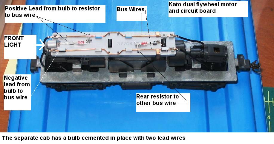
This is the circuit board and chassis of that old ConCor SW7 I picked up a while ago at a flea market. The thing runs very well and is quiet and smooth.
As I opened it up, there is very little to do, except that the cab portion has a bulb cemebted in place with the two wire leads presumably connected to the circuit board. I ran the unit as is on my test track and the front light (bulb, not LED) works forward and backward, varying with current applied, so it is not a constant lighting circuit (as much as I know about that).
The rear bulb connects to the circuit board, but was unattached when I opened up the unit.
Should I just reverse the connection order (from that in the front bulb) and solder the wires
in place (once I test them to see which lead is which on the rear bulb)?
Also, why are there what appears to be resistors in the circuit if it is an incandescent bulb- are they for stepping down the current to enable the buld to last longer?
(these resistors look different from the kind I get at Radio Shack)
I don't see the need to try to put LEDs in this unit, as the front light works fine as is.
See the accompanying photo.
Thanks in advance for any advice.
Siouxlake/Ron
|
Country:  USA ~
Posts: 510 ~
Member Since: September 21 2011 ~
Last Visit: December 21 2014 USA ~
Posts: 510 ~
Member Since: September 21 2011 ~
Last Visit: December 21 2014
|
 Alert Moderator
|
|
|
|
Posted - March 24 2012 : 9:48:17 PM


|
Uh, I can't enlarge the photo enough, but those "resistors" look clear-bodied. Those are probably actual diodes. Diodes use a clear body , or a black with silver band. But you almost NEVER see a clear resistor. Those are reversing diodes for the lights most likely.
Jerry
" When life throws you bananas...it's easy to slip up"
|
|
Country: USA ~
Posts: 3974 ~
Member Since: January 04 2009 ~
Last Visit: January 11 2019
|
Alert Moderator

|
|
|
|
Posted - March 25 2012 : 09:13:21 AM
|
Jerry- they are clear, with one or two color bands- that's why I was not sure what I was looking at.
I looked for more info online, but have not come across anything that addresses the circuit board.
Ron
|
|
Country: USA ~
Posts: 510 ~
Member Since: September 21 2011 ~
Last Visit: December 21 2014
|
Alert Moderator
|
|
|
|
Posted - March 25 2012 : 10:25:00 AM
|
If you have an Ohmmeter , you can check ( without power ) the resistance of those resistor/diodes , by swapping the leads of the meter. If it IS a resistor, the reading will be the same on both sides, if it's a diode, the resistance readings will be different. the small amount of power generated by the meter won't hurt the diodes any going across them like that. That is one sure-fire way to know if they are resistors or diodes, but I'm 99% convinced they are in fact diodes, as I've never seen any engine with resistors in series with dual lights, or any lights. SImple voltage to bulb wiring.
Jerry
" When life throws you bananas...it's easy to slip up"
|
|
Country: USA ~
Posts: 3974 ~
Member Since: January 04 2009 ~
Last Visit: January 11 2019
|
Alert Moderator
|
|
|
|
Posted - March 25 2012 : 5:52:48 PM
|
Have meter, Will check. (a la Palladin)
Ron
|
|
Country: USA ~
Posts: 510 ~
Member Since: September 21 2011 ~
Last Visit: December 21 2014
|
Alert Moderator
|
|
|
|
Posted - March 26 2012 : 05:02:15 AM
|
I finally came across this MR entry when I used the search tool on their forums:
If the Proto 1000 is anything like Proto 2000, the circuit board is just for directional lighting. The diodes on the board drop the output voltage to the lights to lengthen the life of the bulbs. If the engine has LEDs for lights, the diodes also insure that voltage of the correct polarity is fed to the LEDs regardless of track polarity.
The diodes ( not resistors) are just that- to increase the service life of the bulbs. Since they are wired somehow to form a bridge to allow forward/reverse lighting, I will assume that is the case on the rear end of the circuit board and connect the cab lead wires opposite of the front light ones and see if things work right.
This particular model may have been made just before LEDs were introduced to replace bulbs, hence the need for the diodes to make the lighting more durable.
Next time, I will now know more about what I am looking at when I see one of these boards.
Ron
|
|
Country: USA ~
Posts: 510 ~
Member Since: September 21 2011 ~
Last Visit: December 21 2014
|
Alert Moderator
|
|
|
|
Posted - March 26 2012 : 8:23:45 PM
|
quote:
Next time, I will now know more about what I am looking at when I see one of these boards.
Ron
Originally posted by siouxlake - March 26 2012 : 05:02:15 AM
|
Edumacation is a wonderful thing! 
Jerry
" When life throws you bananas...it's easy to slip up"
|
|
Country: USA ~
Posts: 3974 ~
Member Since: January 04 2009 ~
Last Visit: January 11 2019
|
Alert Moderator
|
|
|
|
Posted - March 26 2012 : 9:39:29 PM
|
Ron, those glass buggers are diodes, and they're like a switch for directional lighting, not to extend bulb life. Diodes only have a voltage drop of about 1/2 a volt, so the drop is negligible to a bulb rated at 14 or 16v. The way they're wired here, the bulb will only light in one direction.
In a constant lighting circuit, two diodes in series can steal about a volt from the motor to light a mini 1.5v bulb, which I did for the oil lamp on my Bowker.
The Tyco Depot
|
|
Country: USA ~
Posts: 3927 ~
Member Since: June 20 2007 ~
Last Visit: November 19 2015
|
Alert Moderator
|
|

