|
|
 Posted - February 14 2012 : 7:49:18 PM Posted - February 14 2012 : 7:49:18 PM


|
Many of you have read of AntonioFP45's extensive work with Alclad stainless steel paint on passenger cars in the MR General Forum. Tony is a co-worker and good friend of mine here in Tampa.
I am being treated to his expertise as he repaints my P1K Budd RDC from it's factory paint to the Alclad system he uses. While he is doing this, I have been working on the passenger seating insert and have started to consider lighting the interior.
Another poster on MR, back in 2008, came up with a simple, yet effective system using two LEDs at each end of a white plastic soda straw, with appropriate resistors of course. He further diminished the light by using blue transparent report cover plastic on the inside of the clear window pieces, to great effect.
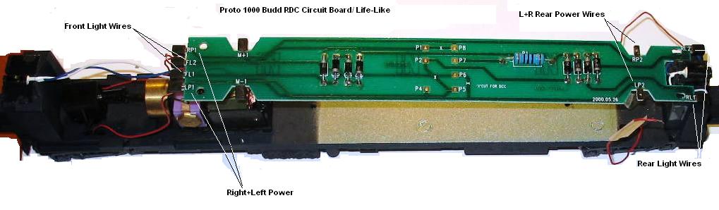
In my case, Life-Like has a circuit board sitting at the ceiling level of my RDC, above the window line. I have included an image, identifying (I think) the various wires that are presently connected to this board.
What I am wondering, is if I could easily connect a pair of wires to this board from the type of lighting system I described above, the question being "where would I connect it?".
The wires are run thru a hole in each terminal and bent in place with a plastic cap, so there is no solder used. There are 8 more connection points in the center of the board (P1 thru P8) that are unused.
I see additional resistors towards both ends of the board. As I am not using DCC, I am not familiar with this stuff. Any held on where I could connect a simple light circuit would be greatly appreciated.
I would have posted this on the MR Forum, but sometimes the responses are either too technical, presuming knowledge I may not have, or a bit snarky also.
Thanks,
Siouxlake/Ron
|
Country:  USA ~
Posts: 510 ~
Member Since: September 21 2011 ~
Last Visit: December 21 2014 USA ~
Posts: 510 ~
Member Since: September 21 2011 ~
Last Visit: December 21 2014
|
 Alert Moderator
|
|
|
|
Posted - February 14 2012 : 7:52:18 PM
|
One other thing...
Yes, I do know about Easy-Peasy and similar modules, such as Miller Engineering and the various LED products out there, but I already have the LEDs, the resistors and can get a white plastic strw from any fast food joint. My general goal is to do things without great expense or fuss, so there you have it...
Ron
|
|
Country: USA ~
Posts: 510 ~
Member Since: September 21 2011 ~
Last Visit: December 21 2014
|
Alert Moderator

|
|
|
|
Posted - February 14 2012 : 8:46:34 PM
|
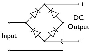
I would tap off of the power from the trucks, and use a diode bridge (4 diodes arranged as below) to keep the interior LED's lit, regardless of direction.
The Tyco Depot
|
|
Country: USA ~
Posts: 3927 ~
Member Since: June 20 2007 ~
Last Visit: November 19 2015
|
Alert Moderator
|
|
|
|
Posted - February 14 2012 : 10:53:48 PM
|
The four resistors grouped together on the PC board appear to be the same thing as a bridge rectifier. My guess is that board is a directional , constant lighting unit, as is.
The points where you have indicated "Lights", I would just measure the voltage there and connect the appropriate size bulb or LED.
Unspoken expectations are premeditated failures.
Edited by - NC shortlines on February 14 2012 11:28:02 PM
|
|
Country: USA ~
Posts: 825 ~
Member Since: December 22 2008 ~
Last Visit: March 16 2015
|
Alert Moderator
|
|
|
|
Posted - February 15 2012 : 06:59:35 AM
|
If those resistors on the board are a bridge rectifier, then would I still need to wire in a 470 or perhaps a 1000 ohm resistor to each LED positive lead at each end of the plastic straw tube, the way I done with other projects previously?
Or, would that bridge compensate for this by itself?
Ron
|
|
Country: USA ~
Posts: 510 ~
Member Since: September 21 2011 ~
Last Visit: December 21 2014
|
Alert Moderator
|
|
|
|
Posted - February 15 2012 : 07:35:37 AM
|
(Please, pardon me, I got my nomenclature wrong). The 4 black things grouped together are diodes. The blue thing with stripes is a resistor that is needed for the lights. I cannot determine the value of it because I'm not sure of the color of the bands.
I think everything is there except the LEDs. All that is needed is to plug in some LEDs in those plastic clips at the ends. Doesn't look like you need anything else. I know someone that can tell you exactly what's going on there and what is needed for lights but, that won't be until Saturday.
Edited by - NC shortlines on February 15 2012 07:36:37 AM
|
|
Country: USA ~
Posts: 825 ~
Member Since: December 22 2008 ~
Last Visit: March 16 2015
|
Alert Moderator
|
|
|
|
Posted - February 15 2012 : 07:38:10 AM
|
| The 4 diodes is essentially the same thing as the drawing that NickelPlate posted.
|
|
Country: USA ~
Posts: 825 ~
Member Since: December 22 2008 ~
Last Visit: March 16 2015
|
Alert Moderator
|
|
|
|
Posted - February 15 2012 : 1:35:42 PM
|
I found the Bevis King website article on DCC installation on this exact circuit board, and he identified the existing resistor as a 300 ohm one. Another article identifies the 4 diodes as a bridge for lighting constancy, but this second article advises swapping out the bulb type lights for LEDs "now" while the unit is open appears to be solid, but recommends replacing the existing 300 ohm resistor with a 470 ohm one, which I am familiar with, to better serve the current reduction requirements.
I think I have enough info to go forward on, and I will share my work-in-progress images of the RDC car interior soon.
Ron
|
|
Country: USA ~
Posts: 510 ~
Member Since: September 21 2011 ~
Last Visit: December 21 2014
|
Alert Moderator
|
|
|
|
Posted - February 15 2012 : 2:17:53 PM
|
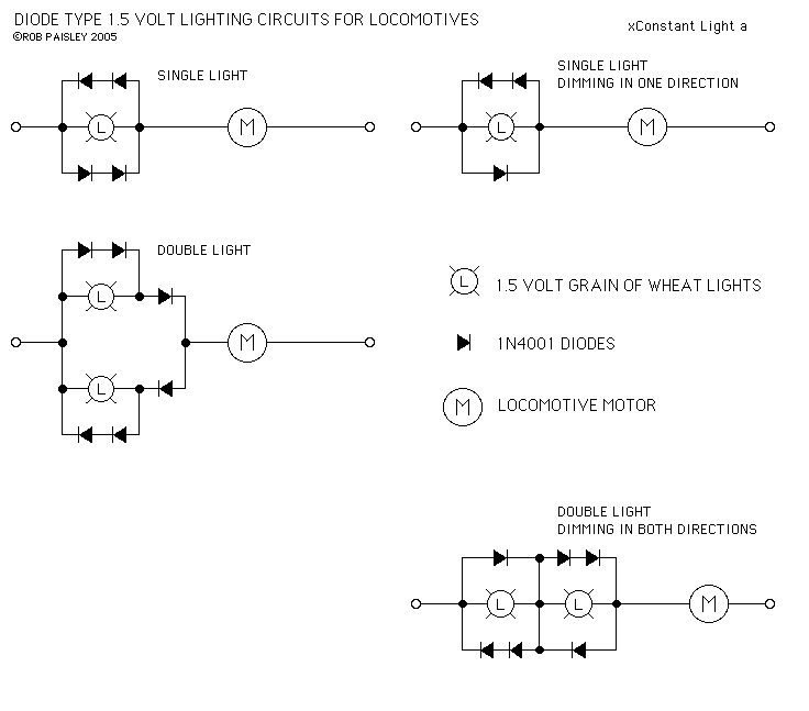
Ron, those aren't diode bridges, they are simple constant lighting circuits, which provide enough of a voltage drop to light the 1.5v bulbs. The resistor is the load or ballast. The polarity to the bulbs probably reverses with track polarity, so putting an LED in the bulb's place would give you directional lighting. I think the diodes for the each headlight are arranged like the circuit in the upper left of this diagram. This circuit is in series with the motor (M), but in your RDC that's substituted with a resistor.
You need a bridge rectifier to make sure you've always got + and - on the appropriate leads of the LED's to keep them lit in both directions for interior lighting, and you would need a current limiting resistor in series with the input to the bridge to protect the LED's as you stated earlier.
The Tyco Depot
|
|
Country: USA ~
Posts: 3927 ~
Member Since: June 20 2007 ~
Last Visit: November 19 2015
|
Alert Moderator
|
|
|
|
Posted - February 15 2012 : 5:02:12 PM
|
Wellllllll (as old Jack Benny used to exclaim)...
Maybe I need to proceed a bit more carefully on this!
I think I will work backwards- build the plastic straw LED interior light first with 470 ohm resistors, test it and set it aside, swap out the existing regular bulbs (assuming that is rally what they are) front and rear with equivalently round end shaped 3mm white LEDs, then build that diode bridge, wire it into the compartment straw light item, connect it as shown by these helpful diagrams, and leave the existing resistor in place to avoid further complications. If that process results in a working interior light and the end car lights are still on when running, I will consider it a done deal.
As the one electronics parts store in Tampa just went out of business in DEC, I guess a quick trip to Radio Shack might get me the diodes and different LEDs I need. I see a cash purchase of about 10 bucks on this, provided I can find a fast food place that actually uses white plastic straws! The grocery store had free ones in black, my employer had red ones....geez, you would think they would be common items!!!!!
Let me know if my plan is a good one.
Ron
PS- just finished mutilating Model Power unpainted figures to fit on those undersized bench seats in the RDC.
Lower torsos, legs everywhere, but not one outcry of pain from the bunch! 
|
|
Country: USA ~
Posts: 510 ~
Member Since: September 21 2011 ~
Last Visit: December 21 2014
|
Alert Moderator
|
|
|
|
Posted - February 15 2012 : 10:35:39 PM
|
Ron, sounds like plan. What's wrong with black straws? Wouldn't they be out of sight anyway?
The Tyco Depot
|
|
Country: USA ~
Posts: 3927 ~
Member Since: June 20 2007 ~
Last Visit: November 19 2015
|
Alert Moderator
|
|
|
|
Posted - February 16 2012 : 05:26:06 AM
|
Nelson- I just don't want to leave those poor mutilated passengers " in the dark " about their destination while riding my rdc!
Ron
|
|
Country: USA ~
Posts: 510 ~
Member Since: September 21 2011 ~
Last Visit: December 21 2014
|
Alert Moderator
|
|
|
|
Posted - February 18 2012 : 8:35:32 PM
|
Ron, I finally realized you're using the straws to hold the LED's. I assumed you were just using them to run wires.
The Tyco Depot
|
|
Country: USA ~
Posts: 3927 ~
Member Since: June 20 2007 ~
Last Visit: November 19 2015
|
Alert Moderator
|
|
|
|
Posted - February 19 2012 : 07:33:10 AM
|
Nelson- that straw lighting idea comes from a researched blog on the MR forum, and is designed to simulate the appearance of florescent lighting. I may or may not use it, after I see how it looks and works. Also, that same poster used translucent blue plastic to further diminish the brightness of the LEDs and make the effect closer to the appearance of passenger cars in the 1950s. I may, in the end, just replace the incandescent front and rear exterior hood lights with LEDs only, if this interior thing is not to my liking, but I will post images and comments as I proceed.
Ron
|
|
Country: USA ~
Posts: 510 ~
Member Since: September 21 2011 ~
Last Visit: December 21 2014
|
Alert Moderator
|
|
|
|
Posted - February 19 2012 : 11:01:44 AM


|
Speaking of interior lighting, 7 years ago I was able to salvage some parts of some fax machines my company was scrapping. One of the items is a strip of light-emitting "somethings", they look like LEDs, square, and gave off a greenish light. They had something to do with causing the toner reaction to the paper. Anyway, they are mounted on small strips of PCB about 8 inches long, with a metal protective strip, about 1/4 inch wide. I was thinking of using them for something similar, either inside a passenger car, or under-roof platform lighting. I forget what voltage caused them to come on, but it was inside the range of model train power supplies, so they'll work. Figured they're dim enough and small enough to be mounted with little hassle. I like the straw and LED concept, I will have to check that out myself.
Jerry
" When life throws you bananas...it's easy to slip up"
|
|
Country: USA ~
Posts: 3974 ~
Member Since: January 04 2009 ~
Last Visit: January 11 2019
|
Alert Moderator
|
|
|
|
Posted - February 19 2012 : 11:42:13 AM
|
Jerry- I remember back in the early 90s, the engineer I worked for had a fax machine that required sheets or a roll of specially treated paper, that felt smooth and waxy to the touch. Perhaps it was photo-sensitive, where the LEDs activated the print powder chemically or some thing like that.
My soon-to-be-college-student genius daughter scared up some plain white straws at a Subway sandwich shop today and I placed one of my Xmas 5mm LEDs in one end. The diffusing cone on the end of the led will have to be sanded or cut, as I have done before and the sides wrapped with shrink (polyolefin) wire wrap to limit light leakage. Right now, the end of the straw is too bright, as light is coming out on the side of the led, rather than projected forward. I had this same issue with the AHM center cab LEDs, so I will try that next.
That soda straw was an exact fit for the 5mm LEDs, so that is a relief!
Ron
|
|
Country: USA ~
Posts: 510 ~
Member Since: September 21 2011 ~
Last Visit: December 21 2014
|
Alert Moderator
|
|
|
|
Posted - February 19 2012 : 5:51:40 PM
|
Ron, I know the guy on the MR forum you're talking about. He did a fantastic job with those interiors and lighting, and even built flicker-free keep alive circuits.
The Tyco Depot
|
|
Country: USA ~
Posts: 3927 ~
Member Since: June 20 2007 ~
Last Visit: November 19 2015
|
Alert Moderator
|
|

