|
|
 Posted - December 26 2011 : 6:52:37 PM Posted - December 26 2011 : 6:52:37 PM


|
Okay- here's that spur of the moment additional project I started:
I picked up an Athearn HO SW7 calf dummy unit at one of the flea markets about 2 yrs ago. As I have been getting some traction with my own railroad, it occurred to me that I have a powered SW7 orphan that is begging to be made into a Siouxlake painted version (and better detailed along the way), but any rework on that will be later on this spring.
The calf dummy is basically a repaint and a few handrails made type of job, so I started to tear it down. Then I thought it would be nice for the headlight to operate. I saw that the wheels are plastic with a metal axle, so new wheels are in order. After a bit of research, NWSL has the right replacement all-metal wheels that are made to replace the old Athearn ones, as per their website.
Now for the harder part- I took apart one wheel/truck assembly and found the following:
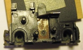
There is a metal strip with a metal rivet thru the acetal (Delrin) plastic truck holding the metal outside frame to the truck itself. If I were to clean these up with fine wet/dry paper, then solder one wire to the single rivet and the other to the metal strip, new all metal wheels should pick up the current from the track and operate an LED with a resistor in series to the positive lead, right?
I saw an article on brass/bronze wipers for steam tender trucks on MR forums, but that is not feasible here.
Any suggestions or comments on this concept?
Thanks,
Siouxlake/Ron
|
Country:  USA ~
Posts: 510 ~
Member Since: September 21 2011 ~
Last Visit: December 21 2014 USA ~
Posts: 510 ~
Member Since: September 21 2011 ~
Last Visit: December 21 2014
|
 Alert Moderator
|
|
|
|
Posted - December 26 2011 : 7:19:30 PM
|
Well, let me be more clear, now that I just re-read my post.
I would run a wire to one rivet on the other side of the truck, as well as a wire to the other side with the metal strip, thereby picking up current from both rails in contact with the all- metal wheels to make a complete circuit.
Ron
|
|
Country: USA ~
Posts: 510 ~
Member Since: September 21 2011 ~
Last Visit: December 21 2014
|
Alert Moderator

|
|
|
|
Posted - December 26 2011 : 7:29:24 PM
|
You have it right, Ron, but the only fly in the ointment is that dummy units usually had plastic axle bearing inserts in the sideframes. I'm not sure if I see green corrosion on yours indicating they're bronze, or just dirty plastic. If they're plastic, you'd have to make bronze wheel wipers.
The Tyco Depot
|
|
Country: USA ~
Posts: 3927 ~
Member Since: June 20 2007 ~
Last Visit: November 19 2015
|
Alert Moderator
|
|
|
|
Posted - December 26 2011 : 10:20:50 PM


|
Yes, you could pick up the power that way, it should work. I'm assuming you're wiping one insulated metal wheel on one side directly, and the metal axle on the other, correct? That would allow the circuit to be completed through the LED and resistor. Don't see a problem with that scenario.
Jerry
" When life throws you bananas...it's easy to slip up"
|
|
Country: USA ~
Posts: 3974 ~
Member Since: January 04 2009 ~
Last Visit: January 11 2019
|
Alert Moderator
|
|
|
|
Posted - December 27 2011 : 01:37:09 AM
|
Nelson-
If you are referring to the circular object directly thru the plastic arch, I scratched that with an Xacto knife and they are metal inserts into the metal side frame on both sides. Both side frame pieces are the same- metal inserts. The wheels have a pointed ending, same as the NWSL all-metal replacements.
Further research on the Walthers site revealed a small inexpensive headlight kit for Athearn BBs, but I figure that a small piece of clear styrene could just as easily sit in the now- empty headlight opening fo no cost and act as a diffuser to the LED. I will use the same 5mm Xmas one as I used on the center cab project. It's warm white and I can cut off the molded- in cone diffuser end og the LED for more direct forward light. I am going to see if I can build a clip, so that the LED will be easy to detach from the hood shell, although I can't imagine why I would open this up ever again. As far as wiring, I would wire it so it is lit when running in reverse (being pushed by the cow powered unit), as it would normally be lit only when not coupled to another car. To figure out a " bridge rectifier " circuit (?) for this simple paint job project would make it way more complex than it deserves.
Another item: I started soaking the shell in SuperClean liquid last night, and the green BN paint is very slow to come off. They must have had a heavy hand on the sprayer with these. I usually have substantial paint softening by 8 to 10 hrs of soak time.
Yet one more item: those side frames are either treated with a chemical weathering, or they have a patina that comes from age ( this model is a 1970s item). Any suggestions on cleaning up the corrosion?
Thanks,
Ron
|
|
Country: USA ~
Posts: 510 ~
Member Since: September 21 2011 ~
Last Visit: December 21 2014
|
Alert Moderator
|
|
|
|
Posted - December 27 2011 : 02:09:12 AM
|
Scratch that last about the round object- one metal side frame uses metal inserts, the other one has
black acetal plastic inserts. Each truck half is a a male to female two piece unit, so I will have to reverse the second truck as it sits in the frame, so that I can wire one lead to each truck on an opposite side that contacts (metal to metal) the other rail. I forgot to mention this as a solution to the plastic insert problem.
No big deal, just a bit longer wire. There is plenty of empty space to work with. I have weighed the frame with the 1/2 oz additional weight the previous owner stuck on it and got 4.2 oz, so that issue is solved, at least.
If my revised solution is in need of further consideration, don't be shy about letting me know.
On a side note: Nelson, that can motor from Howard Moseley (Hobbytown) went in nicely, once I removed a bit of plastic from one end of the AHM GP18 cradle. All I did was to cut 1/8 inch from each shaft, using a vise grip and a saw, and the original linkage matched up exactly in line! I will be posting on that after the cabooses are done. Jeez- I better stop creating more projects and run these current ones to completion before I get workbench laziness syndrome!
Chime in on the apparent final electrical plan...
Ron
|
|
Country: USA ~
Posts: 510 ~
Member Since: September 21 2011 ~
Last Visit: December 21 2014
|
Alert Moderator
|
|
|
|
Posted - December 27 2011 : 02:10:31 AM
|
Scratch that last about the round object- one metal side frame uses metal inserts, the other one has
black acetal plastic inserts. Each truck half is a a male to female two piece unit, so I will have to reverse the second truck as it sits in the frame, so that I can wire one lead to each truck on an opposite side that contacts (metal to metal) the other rail. I forgot to mention this as a solution to the plastic insert problem.
No big deal, just a bit longer wire. There is plenty of empty space to work with. I have weighed the frame with the 1/2 oz additional weight the previous owner stuck on it and got 4.2 oz, so that issue is solved, at least.
If my revised solution is in need of further consideration, don't be shy about letting me know.
On a side note: Nelson, that can motor from Howard Moseley (Hobbytown) went in nicely, once I removed a bit of plastic from one end of the AHM GP18 cradle. All I did was to cut 1/8 inch from each shaft, using a vise
grip and a saw, and the original linkage matched up exactly in line! I will be posting on that after the cabooses are done. Jeez- I better stop creating more projects and run these current ones to completion before I get workbench laziness syndrome!
Chime in on the apparent final electrical plan...
Ron
|
|
Country: USA ~
Posts: 510 ~
Member Since: September 21 2011 ~
Last Visit: December 21 2014
|
Alert Moderator
|
|

