|
|
 Posted - October 21 2011 : 5:03:53 PM Posted - October 21 2011 : 5:03:53 PM


|
NickelPlate759/Nelson, et al:
I was able to easily remove the original plastic worm this morning, using that electricians plier and a second small needle nose plier. I then wiped the shaft clean with 91 alcohol and the chucked a narrow nail set upright in a vise, balanced/placed the back end of the motor shaft on it and gently tapped the new metal worm onto the shaft until flush. I then placed the motor in the cradle and checked the engagement of the top worm gear.
Then I returned to the nail set and used a small hex nut to provide even force on the end of the worm as I gave it a few more gentle taps. The front end of the shaft protrudes out about 1/32 inch at most. When I placed the motor in the chassis cradle and ran power to it from my test track, the motor ran quite smoothly-in fact, at a lower sound level than before. In addition, I was able to visually count the revolutions of the lower gear, which engages the geared wheel at the bottom of the chassis. If I am not mistaken, Nelson, that is what you had referred to in your response to ChrisC's center cab project with respect to slowing the final drive ratio down from "bat out of hell" to a more reasonable "steady walk past the graveyard" (forgive the Halloween euphemisms). The worm engagement appears good.
One final item on the motor- the top and bottom springs which are located under the brass tab solder connection points are only in contact with those tabs by virtue of a spring under each tab, held in contact by the tension of the springs themselves. Is there anything that can be done to reinforce or secure that situation, as I had to stretch one of the springs to make sure it was touching the underside of the tab.
Siouxlake/Ron
|
Country:  USA ~
Posts: 510 ~
Member Since: September 21 2011 ~
Last Visit: December 21 2014 USA ~
Posts: 510 ~
Member Since: September 21 2011 ~
Last Visit: December 21 2014
|
 Alert Moderator
|
|
|
|
Posted - October 21 2011 : 7:51:44 PM


|
What engine make was this, and where did you find the appropriate worm gear for it?
Jerry
" When life throws you bananas...it's easy to slip up"
|
|
Country: USA ~
Posts: 3974 ~
Member Since: January 04 2009 ~
Last Visit: January 11 2019
|
Alert Moderator

|
|
|
|
Posted - October 21 2011 : 8:57:41 PM
|
The loco is an AHM GE 44 ton Center Cab 4 wheel diesel HO model, produced in Yugoslavia by Mehano, a contractor for Rivarossi, among others back in the 1970s and early 1980s. The can motor is a 3 pole fairly generic one with a 2 mm shaft. The original worm and the gearing below it is all acetal plastic (Delrin). The principal issues with this model were one powered/geared wheel and a very high speed due to the gearing ratios as built. NickelPlate 759 replaced the original plastic dual lead worm with a brass single lead Atlas/Kato one that is a drop-in fit. He illustrated this in a reply to ChrisC who showed an extensive rebuild project this past Sept in the AHM forum on this website. The worm change reduces the gear ratio and gives the loco a more reasonable speed range, more appropriate to it's "role" as a small yard or industrial switcher.
As I mentioned in my most recent post to which you replied, the change of the worm I undertook already has demonstrated good effect in motor noise reduction, apparent operating speed slowdown
and reduced vibration.
I obtained the worms from jimmyjnichols@hotmail.com thru his eBay website. I am not sure if he has more of them, but contact him. I originally tried to locate them on the Atlas site, but did not have a part number. Nickelplate759 gave me the guy's website, which I believe is referenced on my earlier thread regarding the worm issue.
This is a real education for me and I am glad I started with a simple engine, such as this one. In a few short weeks, I have obtained enough basic knowledge about engine rebuilding from personal internet research, contact with NWSL/Oso's tech person, and valued assistance from Tyco Forum members such as NickelPlate.
All because I wanted a nice little diesel to run around in my loco servicing/ freight yard layout....
Siouxlake
|
|
Country: USA ~
Posts: 510 ~
Member Since: September 21 2011 ~
Last Visit: December 21 2014
|
Alert Moderator
|
|
|
|
Posted - October 21 2011 : 9:04:22 PM
|
quote:The loco is an AHM GE 44 ton Center Cab 4 wheel diesel HO model, produced in Yugoslavia by Mehano The can motor is a 3 pole fairly generic one with a 2 mm shaft.
Siouxlake
Originally posted by siouxlake - October 21 2011 : 8:57:41 PM
|
Ok, I have a few of those, and definitely would like to get them running better and slower, too. I'll check into finding some of those worms to convert a few of my own AHM 44's
Jerry
" When life throws you bananas...it's easy to slip up"
|
|
Country: USA ~
Posts: 3974 ~
Member Since: January 04 2009 ~
Last Visit: January 11 2019
|
Alert Moderator
|
|
|
|
Posted - October 21 2011 : 9:13:34 PM
|
Ron, glad to hear it went so well. I'm surprised you had to stretch one of the brush springs, because they have to be compressed a lot -- at least a third of their length, IIRC -- in order to slide the retainer plate back into place. The brushes are under more tension than they need to be, as the springs are quite stiff. I've looked for a suitable replacement spring made from thinner gauge wire, but I haven't had any luck. If you had to stretch one out, it was either cut short by someone else, or it heated up under extreme load and collapsed.
One thing I would recommend is to keep all of your updates in one thread so everyone can follow along, instead of creating new ones each time.
The Tyco Depot
|
|
Country: USA ~
Posts: 3927 ~
Member Since: June 20 2007 ~
Last Visit: November 19 2015
|
Alert Moderator
|
|
|
|
Posted - October 21 2011 : 10:36:07 PM
|
Thanks for the support, Nelson- and the tip on maintaining forum continuity, so I will just keep it here with this thread. I may have inadvertently fiddled a bit with the springs when I removed the brass tabs to degrease and clean them, but solved the problem anyway.
Now that the motor issue is resolved, on to getting two LEDs fore and aft fitted inside the upper shell.
I prepared new wires for the motor, which are to be soldered to the pickups along each side of the chassis, using 24 gauge multi strand wire, red and black. The original bulb light had a much smaller gauge wire attached, which was as decayed as the original motor wires, probably a 30 gauge, if I am looking at it right.
The 24 gauge presents too bulky a fit issue to wire the LEDs, so back to the electronics parts store near work to see if they have a thin wire.
Radio Shack only had 24 at the smallest, and the home building stores, Walmart, and Ace Hardware also seem not to have small wire. But- I am thinking that doorbell wire is pretty thin, so maybe I will luck out. I have a
large supply of .20Ma 5mm warm white LEDs I got from Walmart last Xmas and by positioning one of each with a 470 ohm resistor on each positive lead, it should work okay. These have an inverted cone molded in to spread the light, so that should be sufficient to send light thru each of the parallel lenses on each end of the shell. I gouged out some space for the led on the larger weight and will probably shrink wrap the bases of each led as I do the soldering to minimize light leakage. Speaking of which, this model has vertical see thru grilles on each side of the shell at each end, so covering them on the inside after the painting is done wouldn't hurt. I already painted the lead weights flat black to help cut down light leakage.
Those lead weights sit loose in the chassis, but some foam double stick tape should quiet them down as well as stabilize them. If future disassembly is needed, the foam tape is easily removed.
I could probably get 3 mm LEDs that would be better, but the goal is to make do mostly with what I have on hand, so that the total expense of the project is minimal.
I am imaging this work as I go, so one of these days- hopefully, right after Thanksgiving, I will post the whole done deal.
Siouxlake
T
|
|
Country: USA ~
Posts: 510 ~
Member Since: September 21 2011 ~
Last Visit: December 21 2014
|
Alert Moderator
|
|
|
|
Posted - October 22 2011 : 09:24:33 AM
|
would love to see pics of this projet....didn't even know AHM made a 44!
just me Ray... and just because I have Tyco doesn't mean I am not a model railroader
|
|
Country: USA ~
Posts: 506 ~
Member Since: April 03 2011 ~
Last Visit: November 29 2025
|
Alert Moderator
|
|
|
|
Posted - October 22 2011 : 09:55:54 AM
|
hi rgcw5 link for ge ken
http://www.ho-scaletrains.net/ahmhoscalelocomotives/id28.html
|
Country:  United Kingdom ~
Posts: 8294 ~
Member Since: September 28 2006 ~
Last Visit: October 20 2021 United Kingdom ~
Posts: 8294 ~
Member Since: September 28 2006 ~
Last Visit: October 20 2021
|
Alert Moderator
|
|
|
|
Posted - October 22 2011 : 3:16:58 PM
|
Solved the led wire issue- those little wired rail joiner feeders that you get from Atlas- and of which I happen to have a bunch- have multi strand wire sufficiently long enough to use as smaller gauge wiring for the lights.
The idea was staring me in the face, as I use 2 of them to connect my test track to a small TYCO power supply. No need to go to another shop when what's in your own is already there! (did that confuse anybody?)
Now, I will fire up the soldering iron and start getting things wired up!
Siouxlake
|
|
Country: USA ~
Posts: 510 ~
Member Since: September 21 2011 ~
Last Visit: December 21 2014
|
Alert Moderator
|
|
|
|
Posted - October 22 2011 : 6:13:37 PM
|
Ron, I strip the wiring harnesses out of old electronics when I scrap it, like VCR's and such I find at the curb. It comes in very handy.
The Tyco Depot
|
|
Country: USA ~
Posts: 3927 ~
Member Since: June 20 2007 ~
Last Visit: November 19 2015
|
Alert Moderator
|
|
|
|
Posted - October 22 2011 : 9:49:31 PM
|
Never thought of that- there are a bunch of old electronics, computers in junked mode at my school. I should start cannibalizing now to stock up! Outstanding idea! Not that I am a pack rat or anything like that...
Siouxlake/Ron
|
|
Country: USA ~
Posts: 510 ~
Member Since: September 21 2011 ~
Last Visit: December 21 2014
|
Alert Moderator
|
|
|
|
 Posted - October 22 2011 : 10:05:15 PM Posted - October 22 2011 : 10:05:15 PM
|
Nah, none of us here are like that... 
http://www.tycoforums.com/tyco/forum/topic.asp?TOPIC_ID=9669
The Tyco Depot
|
|
Country: USA ~
Posts: 3927 ~
Member Since: June 20 2007 ~
Last Visit: November 19 2015
|
Alert Moderator
|
|
|
|
Posted - October 23 2011 : 05:44:58 AM
|
quote:
ah ok yes i have seen it before but to clear the confusion that model is actually a Plymouth CR-4 (or close resemblence)
thanks ken
Ray
just me Ray... and just because I have Tyco doesn't mean I am not a model railroader
|
|
Country: USA ~
Posts: 506 ~
Member Since: April 03 2011 ~
Last Visit: November 29 2025
|
Alert Moderator
|
|
|
|
Posted - October 23 2011 : 08:00:06 AM
|
I have an image of that Plymouth CR-4 in my database. The AHM folks must not have liked the angled ends on the real one and homogenized their model quite a bit. Either way, it "looks" like a credible yard or industrial plant switcher. Given that I am adding a few unusual details as did ChrisC, not to mention figuring out a color scheme for my own railroad, straying from reality is excusable in our hobby.
Latest: I put some heat shrink material around one of those 5 mm LEDs last night and will dummy up an active circuit to test the way the light spreads from the end, given the built-in 30 degree diffusing cone. I could have just painted it flat black on the side, but found that the heat shrink sleeve is better for mounting with foam tape and looks a bit less amateurish and more "hobby-professional".
Souixlake/Ron
|
|
Country: USA ~
Posts: 510 ~
Member Since: September 21 2011 ~
Last Visit: December 21 2014
|
Alert Moderator
|
|
|
|
Posted - October 23 2011 : 08:42:27 AM
|
hi guys i just read on a site that mantua used cr-4 tooling for this ken
http://www.hoseeker.net/mantuainstructions/mantuaplymouthyarddieselinstr.jpg
this was the site
http://www.guidetozscale.com/html/athearn_hustler.html
real cr-4
/tyco/forum/uploaded/catfordken/20111023084643_lbr3a-1.jpg
mantua
/tyco/forum/uploaded/catfordken/20111023085602_78_09_Mantua.jpg
ahm
/tyco/forum/uploaded/catfordken/20111023090347_ahm.jpg
Edited by - catfordken on October 23 2011 09:03:59 AM
|
|
Country: United Kingdom ~
Posts: 8294 ~
Member Since: September 28 2006 ~
Last Visit: October 20 2021
|
Alert Moderator
|
|
|
|
Posted - October 23 2011 : 08:50:21 AM
|
That is not the same model as the AHM, but the resemblance is interesting, but the motor and gearing are significantly different, with two geared wheels instead of one. It may have had a more robust pulling power, but the lack of weight might have offset that.
Siouxlake/Ron
|
|
Country: USA ~
Posts: 510 ~
Member Since: September 21 2011 ~
Last Visit: December 21 2014
|
Alert Moderator
|
|
|
|
Posted - October 23 2011 : 09:06:10 AM
|
Just completed the LED test and the shrink tubing does a good job of eliminating stray light. I placed the shell with the plastic lens over the LED and there was sufficient light coming out to illuminate both parallel lens holes. Of course, the light was brighter with more power applied. I used a 470 ohm resistor in this test. I had picked up some 1000 ohm (yeah, I know it's cited as 1K) resistors, but will not use them in this project, as the 470 ohm appears sufficient for the purpose.
One thing- the LED lights only when power is applied in one direction. When I reversed the test lead wires and then applied power in the opposite direction, the LED lit up.
So.... How do I wire up each LED so they both stay lit in either direction? Or should I just do the simple thing and wire them the plain way so each lights up individually in the direction of travel?
Help!
Siouxlake/Ron
|
|
Country: USA ~
Posts: 510 ~
Member Since: September 21 2011 ~
Last Visit: December 21 2014
|
Alert Moderator
|
|
|
|
Posted - October 23 2011 : 09:09:03 AM
|
CatfordKen- in my last post about your research, I was referring to the Mantua Plymouth model, not the AHM you showed as the final image in your post.
Ron
|
|
Country: USA ~
Posts: 510 ~
Member Since: September 21 2011 ~
Last Visit: December 21 2014
|
Alert Moderator
|
|
|
|
Posted - October 23 2011 : 09:36:48 AM
|
| hi ron,understand,just found the info and ahm photo,ken
|
|
Country: United Kingdom ~
Posts: 8294 ~
Member Since: September 28 2006 ~
Last Visit: October 20 2021
|
Alert Moderator
|
|
|
|
Posted - October 23 2011 : 2:47:22 PM
|
LONG LIVE PLYMOUTH! Im going to mod an switcher I got yesterday.
|
|
Country: USA ~
Posts: 1102 ~
Member Since: July 28 2011 ~
Last Visit: July 01 2015
|
Alert Moderator
|
|
|
|
Posted - October 25 2011 : 6:27:46 PM
|
I checked out the LED light spread behind the center cab shell front lens and determined that it produced sufficient forward lighting to adequately do the job with a 470 ohm resistor wired in.
Then I noticed that there was some side light leakage thru the vertical grills on each side of the shell, so in glued a very thin piece of styrene on the insides to stop this.
But wait, there's more! I noticed that the front led lit up in forward throttle, but remained dark in reverse. Then question then becomes, if I reverse the positive & negative lead connections on a REAR LED, will it work when the throttle is reversed and the loco moves backward?
I know some may say why bother? But the existence of an identical headlight lens on the rear of the loco begs for lighting as well. In my fictitious ( but ever so real servicing terminal/switching yard ), it might be a good safety practice to have that rear light operating when reversing to pick up a few cars.
Any feedback on the reverse wiring?
Siouxlake/Ron
|
|
Country: USA ~
Posts: 510 ~
Member Since: September 21 2011 ~
Last Visit: December 21 2014
|
Alert Moderator
|
|
|
|
Posted - October 25 2011 : 8:57:37 PM
|
quote:
Any feedback on the reverse wiring?
Siouxlake/Ron
Originally posted by siouxlake - October 25 2011 : 6:27:46 PM
|
yes, it's called a Bridge Rectifier circuit. 4 diodes in a square , end to end, power comes in one way ( say, horizontal ), and the lighting LEDs take power off the vertical feeds. Here's a link to some sites that may help -
http://cs.trains.com/TRCCS/forums/p/47096/596562.aspx
RE: Bi-Directional LED Lighting
hd8091 replied on Wed, Oct 12 2005 1:01 AM
Here are some web sites which will help you:
http://www.mrollins.com/circuit.html
http://halloween.sitenation.com/site/view/article/1011997374/ca
http://www.reprise.com/host/circuits/default.asp
http://www.pollensoftware.com/railroad/
http://www.hobby.se/Rutger/Rutger.html
THis might help, don't know since I haven't checked any of the sites out, but the rectifier circuit is what you'll need to do that.
Jerry
" When life throws you bananas...it's easy to slip up"
|
|
Country: USA ~
Posts: 3974 ~
Member Since: January 04 2009 ~
Last Visit: January 11 2019
|
Alert Moderator
|
|
|
|
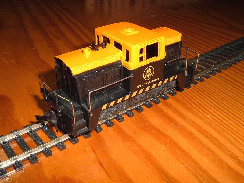
Posted - October 25 2011 : 10:44:28 PM
|
I bought one of the Tyco Plymouths at a train show for about $20 becuase it's decorated for the Bell System, which I think is really cool. It has a good deal of weight for its size because it has diecast end weights and sideframes, in addition to the chassis, so it pulls well.
The Tyco Depot
|
|
Country: USA ~
Posts: 3927 ~
Member Since: June 20 2007 ~
Last Visit: November 19 2015
|
Alert Moderator
|
|
|
|
Posted - October 26 2011 : 05:25:40 AM
|
quote:I bought one of the Tyco Plymouths at a train show for about $20 becuase it's decorated for the Bell System, which I think is really cool.
Originally posted by NickelPlate759 - October 25 2011 : 10:44:28 PM
|
You don't see those Bell shells too often. I think I have 5 of these T227's, UP, USSteel, and plain black one, and two red ones. Nice little units.
Jerry
" When life throws you bananas...it's easy to slip up"
|
|
Country: USA ~
Posts: 3974 ~
Member Since: January 04 2009 ~
Last Visit: January 11 2019
|
Alert Moderator
|
|
|
|
Posted - October 26 2011 : 07:53:21 AM
|
Show The US Steel One! ME LIKEY!
|
|
Country: USA ~
Posts: 1102 ~
Member Since: July 28 2011 ~
Last Visit: July 01 2015
|
Alert Moderator
|
|
|
|
Posted - October 26 2011 : 7:32:14 PM
|
I am a genius!....well, I think I'm sorta smart....er,uh I have my moments...I repeated my bench test of the LED wired with a 470 ohm resistor, but this time, I prepared a second one, in identical fashion. I used black and red wires with alligator clips. The first LED circuit was clipped to the rails of my test track with the red on one and the black on the other rail; the second LED circuit was clipped in reverse manner to the first. When I moved the throttle one way, one LED lit up- when I moved the throttle the other direction, the OTHER LED lit up, so there is my forward and reverse lighting system for the center cab project!!!
Now, my principal task will be to do the soldering and shrink wrapping properly to ensure that each LED circuit will be positionable behind each of the headlight lenses properly. I ran the test in my garage workshop with the lights off and the amount of light on this 470 ohm setup was sufficient at low throttle and very bright as it neared full power. The only test remaining will be to swap out a 1K ohm resistor in one circuit to compare the brightness levels of each one before I commit to soldering.
I know this stuff may sound pretty lame and simple to others, but these little learning episodes are what makes the hobby fun. And who knows, perhaps there is another railroader out there stumbling along a similar path who can benefit from my experiences.
Now, enough with the fun- time to take the ferocious poodle out for his constitutional!
Siouxlake/Ron
|
|
Country: USA ~
Posts: 510 ~
Member Since: September 21 2011 ~
Last Visit: December 21 2014
|
Alert Moderator
|
|
|
|
Posted - October 26 2011 : 8:06:13 PM
|
Just couldn't let things go without doing that LED resistor comparison test. Turns out that (with the garage workshop lights out) it was hard to tell much difference between the 470 ohm and the 1K ohm circuit brightness. There was some slight difference, but not enough to justify using the larger value resistor.
A while back, an article in MRH online magazine showed a modeler who set up a testing station for LEDs for structure lighting, but that calls for a bit more fine tuning of lighting values than I am dealing with here.
Also, I am using just a simple warm white LED, generic enough to pass for headlamp color of the transition era, which I try to stick with on my modest layout.
By the way, the poodle witnessed both lighting tests, so if you need a second opinion...
|
|
Country: USA ~
Posts: 510 ~
Member Since: September 21 2011 ~
Last Visit: December 21 2014
|
Alert Moderator
|
|
|
|
Posted - October 30 2011 : 8:09:51 PM
|
Well, got out the ordering iron and went to work on the motor and the headlight LEDs. The simple trick of reversing the leads on the LEDs for the rear lighting worked fine- no fancy diode bridge or anything else that might not fit well in the small clearances I have on the Center Cab.
When I put the weights on and tested the power chassis, it ran very smooth and hummed, rather than buzzed as it did before. Nickelplate759/Nelson's metal replacement worm is a winner! The front led lit up in forward and the rear one lit up in reverse, so back to the paint shop to get the shell and lower deck ready. I used Walmart Colormate gray primer on the lower deck and let it dry overnight, then shot it with my final rusty red color. The shell is a combo of the rusty red and GN Orange, but I will also use the orange to highlight the decking edges and step areas, as ChrisC did.
Looks like this turkey will be done before Thanksgiving- then I can bug Nelson about those 2 Plymouth MDTs
that are patiently waiting off stage for their makeovers.
I am cleaning up all my progress images and will let folks know when they are ready- probably will post them to Flicker or something and give an executive summary of the project here.
Oh yeah, sorry about the snow up north, it was just a bit breezy and cool this week end here in Florida!
(shoveled for over 2 decades- don't miss it a bit).
Siouxlake/Ron
|
|
Country: USA ~
Posts: 510 ~
Member Since: September 21 2011 ~
Last Visit: December 21 2014
|
Alert Moderator
|
|
|
|
Posted - October 30 2011 : 8:43:56 PM
|
Looks like the Mantua is more to scale and accurated than the AHM. Is that Plymouth have any relations to the Plymouth car?
" Heck with counting 'em rivets, TRAINS ARE FOR FUN! Not called the Mad Scientist for nothing either!"
|
|
Country: USA ~
Posts: 3147 ~
Member Since: May 07 2007 ~
Last Visit: June 01 2026
|
Alert Moderator
|
|
|
|
Posted - October 30 2011 : 10:00:04 PM
|
quote:Well, got out the ordering iron and went to work on the motor and the headlight LEDs. The simple trick of reversing the leads on the LEDs for the rear lighting worked fine- no fancy diode bridge or anything else that might not fit well in the small clearances I have on the Center Cab.
Siouxlake/Ron
Originally posted by siouxlake - October 30 2011 : 8:09:51 PM
|
did you use current-limiting resistors? Or just straight power to the LEDs? If so, they won't last long. While technically LEDs ARE diodes, they're not really designed to resist reverse voltage, so they won't last if you didn't put current limiting resistors and true diodes in series with them. Enjoy it while it lasts.
Jerry
Electronic Tech.
" When life throws you bananas...it's easy to slip up"
|
|
Country: USA ~
Posts: 3974 ~
Member Since: January 04 2009 ~
Last Visit: January 11 2019
|
Alert Moderator
|
|
|
|
Posted - October 30 2011 : 10:00:52 PM
|
quote:Show The US Steel One! ME LIKEY!
Originally posted by CNVIATyco - October 26 2011 : 07:53:21 AM
|
It's already in the post about the Matchbox Shunter project, the blue one.
- EDIT - Oops, that is a Republic Steel, not US . My bad. 
Jerry
" When life throws you bananas...it's easy to slip up"
Edited by - AMC_Gremlin_GT on October 30 2011 10:04:02 PM
|
|
Country: USA ~
Posts: 3974 ~
Member Since: January 04 2009 ~
Last Visit: January 11 2019
|
Alert Moderator
|
|
|
|
Posted - October 31 2011 : 04:57:06 AM
|
To Redneck- I have read about the scaling issue with the Plymouth MDTs, but they are small and look effective on a small switching layout, so why not give them an upgrade to resolve their overspeed issues. Besides, there is a Midwest Central Railroad (Iowa) on you tube that has a real one which looks amazingly just like the AHM/TYCO/Model Power ones, so life must have imitated art somewhere along the line- the railroad line, that is!
To Jerry- I forgot to mention, it may have been in earlier posts, I used one 470 ohm resistor soldered to each of the positive LED leads (front and back). I tested a 1K resistor but did not see any significant lighting difference as I ran the throttle up to full 12v dc power, so I used the warm white 470s (5mm) I salvaged from a Walmart Xmas tree string ($6 for a string of 50!). These are not meant to focus down the track per se, as there are 2parallel light lenses on each end of the center cab, and the LED serves to distribute light thru the original plastic lens piece that plugs those parallel holes. The LED illuminates each lens hole sufficiently to represent working headlights, hence the reason I was fiddling with a larger value resistor before committing to the 470ohm ones.
At any rate, the "TYCO" transformer attached to my test track is not exactly an example of precision, but when I use my layout MRC power supply, the throttling will be more fine and incremental, with respect to the motion of the locomotive and the light generation.
Gotta get out to beat traffic to work!
Siouxlake/Ron
|
|
Country: USA ~
Posts: 510 ~
Member Since: September 21 2011 ~
Last Visit: December 21 2014
|
Alert Moderator
|
|
|
|
Posted - October 31 2011 : 7:18:14 PM
|
Good work, Ron. I thought two LED's in series could work as reversing diodes for each other, but I hadn't tried it yet. I have a ton of super bright LED's that I got on eBay a few years ago, but they're all bluish-white. The seller's picture was a bit deceiving. Tinting them only makes the color unnatural and kind of ghastly.
The AHM's are better repowering fodder. There's not much you can do with an MU-2 drive. At least they have both axles driven, but there's nothing you can do about the speed and noise. Doing a neodymium magnet replacement will slow them down some.
Btw, I found this dead ringer for the Plymouth MDT, minus the front porch.
/tyco/forum/uploaded/NickelPlate759/5730.1094453220.jpg
http://www.railpictures.net/viewphoto.php?id=76874&nseq=159
The Tyco Depot
|
|
Country: USA ~
Posts: 3927 ~
Member Since: June 20 2007 ~
Last Visit: November 19 2015
|
Alert Moderator
|
|
|
|
Posted - October 31 2011 : 7:39:52 PM
|
WHERE IS THE DRULING EMOTICON! AWESOME PLYMOUTH MDT! My favorites of the Plymouth gang! Then it is WDT Followed by DDT.
|
|
Country: USA ~
Posts: 1102 ~
Member Since: July 28 2011 ~
Last Visit: July 01 2015
|
Alert Moderator
|
|
|
|
Posted - November 01 2011 : 6:23:36 PM
|
That logo on the cab side looks familiar- could be the same Iowa Plymouth MDT I saw on You Tube. I have the image you attached as well, in addition to a bunch of others. I firmly believe in doing research before starting anything. I have found that process invaluable in my previous work on over 25 structures for my layout, as the info I obtain often guides the modeling choices I make in the construction process. When you and the boys see the reversed muffler on the AHM center cab, as opposed to ChrisC's forward elephant trunk style, that position is based on photo images of other industrial diesel switchers found online.
If this reverse LED logic holds, then it will be applicable to other projects down the line. That will make it feasible to innovate lighting to recreate real railroad equipment better.
Gotta go walk the dog before NCIS!
Siouxlake/Ron
|
|
Country: USA ~
Posts: 510 ~
Member Since: September 21 2011 ~
Last Visit: December 21 2014
|
Alert Moderator
|
|