|
|
 Posted - February 05 2019 : 09:07:35 AM Posted - February 05 2019 : 09:07:35 AM


|
For the last couple of decades I've dreamed of doing a pure point-to-point subway layout. A friend
sent me an exquisite MTH dummy subway car this Christmas past, and as luck would have it,
it appears about identical to the subways I rode with Dad on a trip to NYC back in the early '70's.
Game on, I got a matching powered unit, a length of PVC pipe, gathered up some code 83 Atlas
Tru Track, and finally, the only components I could find that would automatically reverse and pause
the train. That I could only find in the UK from Heathcote Electronics.
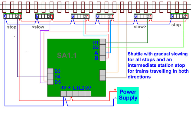
Clive, kindly sent me ten pages of schematics, including one handwritten one. After about the first
paragraph, the information within appears to be about like this:

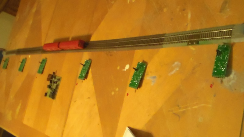
That being said, here's what I got on the workbench:
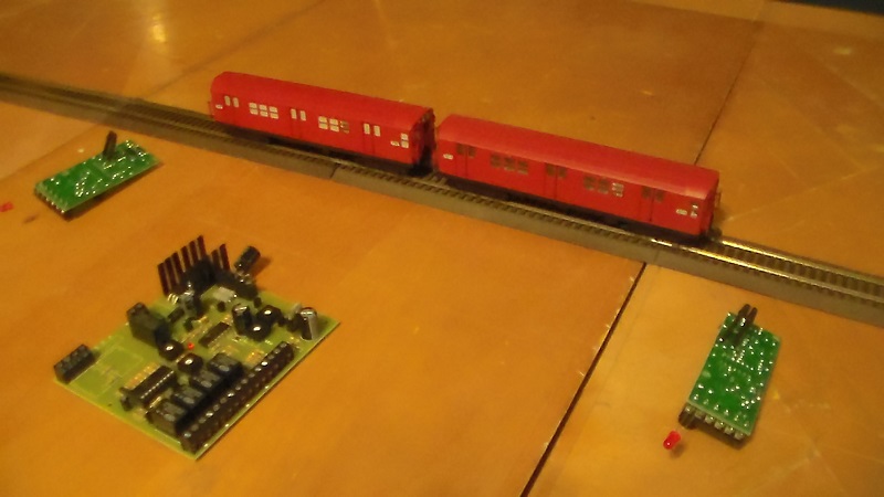
What needs to happen is:
Train goes to center. Stops for five seconds. Train goes to right, to end, stops, reverses. Train goes to center. Stops for five seconds. Train continues left, to end, stops, reverses. Train travels right to center, stops for five seconds, and continues on.
Back and forth with a stop in middle.
Any ideas how to wire this up? Ideally, the power would come from one power pack.
The sensors are infrared. Are they black stalks on the back of the IRDOT?
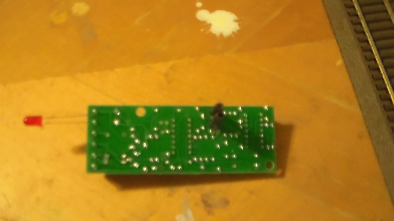
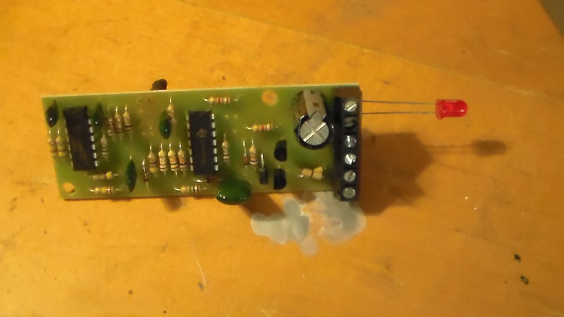
Do those sensors go through a hole in the road bed and sense the train passing overhead?
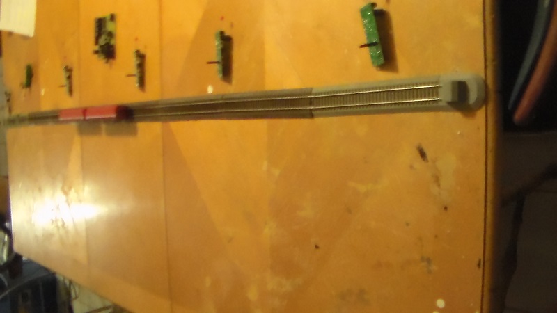
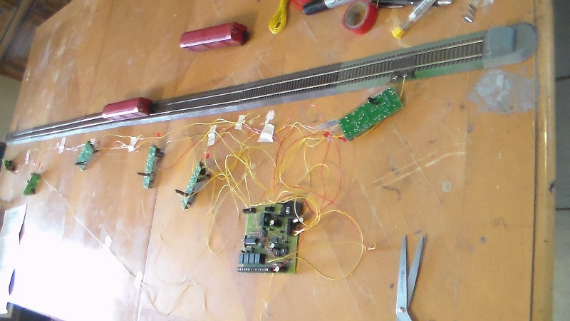
Once the track is properly wired and sensored, then it will be slipped permanently into a length of PVC tube.
I'll worry about third rails and details later. Essentially, there will be an open section within the six foot
length of PVC tube featuring the subway platform.
|
Country:  USA ~
Posts: 11686 ~
Member Since: December 09 2013 ~
Last Visit: May 26 2026 USA ~
Posts: 11686 ~
Member Since: December 09 2013 ~
Last Visit: May 26 2026
|
 Alert Moderator
|
|
|
|
Posted - February 05 2019 : 4:26:55 PM
|
A green horn when it comes to wiring. Why I like Tyco. Two wires, two rails. I can do that. I think I
understand this schematic, but can anyone with know-how verify this looks right? Thanks.
|
|
Country: USA ~
Posts: 11686 ~
Member Since: December 09 2013 ~
Last Visit: May 26 2026
|
Alert Moderator

|
|
|
|
Posted - February 06 2019 : 4:51:58 PM
|
Well, not as bad as I thought. The hardest part was keeping track of the wires as they went in, so as to
not confuse them. Only had two colors to work with. I might have tagged them, and probably should.
Held my breath and turned it on. Nothing.
Flipped the reverse switch and all the lights began to glow and blink in sequence. Put the car on and
it gently rolled to one end and bumped the bumper. Next step will be to install the sensors under the
track. Will have to guestimate the proper spacing and then see if the stopping distance can be adjusted
with one of two set screws under the main circuit board.
|
|
Country: USA ~
Posts: 11686 ~
Member Since: December 09 2013 ~
Last Visit: May 26 2026
|
Alert Moderator
|
|
|
|
|
|
