|
|
 Posted - December 11 2015 : 8:44:44 PM Posted - December 11 2015 : 8:44:44 PM


|
I've read up a bit on first generation steam, of late. One question continues to
frustrate me: the water cask in the tender of the famous "Rocket." In the early
19th century, in the presumptive absence of high pressure flexible hoses, how
was water transmitted from the water reservoir to the boiler?
And given that the boiler pressure was operating at about 40 psi, what kind of
pump or injector did Stephenson use to prevent a back flow of steam pressure
into the water reservoir (if any)?
Lastly, was the wooden shell over the boiler an early means of containing heat
in the boiler?
I did discover the answer to one vexing question, and that was
how did prototype 19th high pressure boilers get tested before
being pumped up with live steam. And that applies to the Rocket: they
had sufficient pump technology to actually perform a "hydrostatic test"
pumping the boiler full of cold water and inspecting for leaks and
bulging boiler plates, and that at least with the "Rocket," mercury
gauges were fairly sophisticated by this point for reckoning PSI.
Another curious footnote: for a period of time I have read that
high pressure steam was illegal in the early days of steam power
and vacuum stationary steam engines. I have not seen the actual
source reference to this alleged "law," but has anyone else heard
or seen of this?? And was it ignored or overturned with Trevethick's
or Watt's early high pressure boilers ?
Edited by - Chops124 on December 11 2015 8:53:17 PM
|
Country:  USA ~
Posts: 11686 ~
Member Since: December 09 2013 ~
Last Visit: May 26 2026 USA ~
Posts: 11686 ~
Member Since: December 09 2013 ~
Last Visit: May 26 2026
|
 Alert Moderator
|
|
|
|
Posted - December 11 2015 : 10:30:51 PM
|
Water was fed to the boiler via a hand operated pump. I'm not sure of the pump's location, but if it was mounted on the locomotive, it could be plumbed to the boiler with pipes rather than hoses, so high pressure hose would not be strictly necessary.
The wood around the boiler would serve as insulation to cut the heat loss through the shell of the boiler. There's a noticeable difference in firing a poorly insulated boiler and a well insulated one.
Carpe Manana!
|
|
Country: USA ~
Posts: 2418 ~
Member Since: September 17 2013 ~
Last Visit: July 17 2026
|
Alert Moderator

|
|
|
|
Posted - December 12 2015 : 10:31:50 AM
|
So, the hand pump theory makes sense,
but what of the flexibility of the pipe going
to the boiler? Lateral movement and
vertical movement would stress the
connection points.
Along this line, of up/down/side-to-side
motion along uneven rail, suspension
was quite an issue. The cast iron leaf
springs of the day were too brittle to
support the seven ton weight of the
Rocket. Some early locomotives
routinely shattered the cast iron
rail between their excessive weight
(12 tons, thereabout) and their
unsprung chassis. Again, Stephenson
pioneered locomotive suspension to
spare the rail.
Exactly how, I seem to forget. Had something
to do with weight distribution and the light
(comparatively speaking) weight of the
locomotive unit. Also, something to do with
the angle of the pistons and how they
connected to the driving wheels. Earlier models
used a series of rods to reduce the hammering
motion of the drive wheels. Stephenson refined
all this. I have to go review my
source material on all that.
Never the less, one may deduct that if they had
sufficient pumps/valves to do
hydrostatic tests, then certainly
they had a tight enough fitting
back flow valve to retain the
pressure of steam in the boiler.
One takes for granted something like
high pressure hoses, but these guys
were building this stuff from scratch,
from the raw ore up. Beef tallow was
used for lubricant and oakum used
for piston ring packing to trap the
steam in cylinders. So what flexible
tube did they use to connect the tender
and locomotive? Not something they
could buy off the shelf, I assume.
Edited by - Chops124 on December 12 2015 10:41:55 AM
|
|
Country: USA ~
Posts: 11686 ~
Member Since: December 09 2013 ~
Last Visit: May 26 2026
|
Alert Moderator
|
|
|
|
Posted - December 12 2015 : 10:47:30 AM
|
Another bit, Stephenson is also credited with the
development of modern railroad track with regard
to turnouts and crossings. Stephenson's early
work involved extensive colliery (coal mine) design
and management, and he patterned railroad track
after coal wagon track, used in the tunnels.
The genius of this man cannot be overstated.
Edited by - Chops124 on December 12 2015 10:55:33 AM
|
|
Country: USA ~
Posts: 11686 ~
Member Since: December 09 2013 ~
Last Visit: May 26 2026
|
Alert Moderator
|
|
|
|
Posted - December 12 2015 : 6:44:34 PM
|
All I've seen as a fact is that the water went from the cask to the boiler through a pipe under the engine, and that there was a check valve (then called a flapper), and a hand pump. There would only be boiler pressure from the boiler to the flapper. From the pump to the flapper, there would be hydrostatic pressure greater than the boiler pressure. From the cask to the pump, there need only be the pressure of the water from the top of the cask to the lowest point between the cask and the pump. That would not be much. If the pump was on the locomotive, not the tender, the flexible fitting (the hose) would have little pressure to hold. The stuff I read did not tell the location of the pump.
As for the hammer on the rail, one of the innovations of the Rocket was that the cylinders were not vertical, but closer to horizontal eliminating much of the hammer on the tracks.
Concerning weight, I read that the Rocket had 2.5 tons on the drivers out of 4.5 tons total. That's heavy for the rails of the time, but nothing compared to modern railroad equipment. As you say, developing these things was very much a process.
Carpe Manana!
|
|
Country: USA ~
Posts: 2418 ~
Member Since: September 17 2013 ~
Last Visit: July 17 2026
|
Alert Moderator
|
|
|
|
Posted - December 13 2015 : 12:22:16 AM
|
One image, of uncertain age, shows some hose fixture
between tender and locomotive. The "flapper" theory lot of sense. A quick search of google shows that prior to 1821 hoses were made of leather. In
1821 a cotton fabric reinforcement to a rubber hose was patented.
Scsshaggy's answer about the wood being used as insulation is entirely supported
by the 19th century articles I've located. It was one inch thick staves. There is a
mention of the firebox being made of copper, as it was thin and allowed good
heat transfer, and tolerated temperature fluctuations, whilst cast iron could be
used but had a tendency to crack to leak with age.
Another article from the 19th century regarding the successor "Planet" makes
mention of two, not one, feeder pumps, the second being a fail safe back up.
A woodcut from an 1829 "Mechanics Magazine shows much detail, but does
not show anything other than a link between locomotive and tender. The
cask could be for beer, for all one can tell.
I wasn't too far off on the total weight package. "The Railway Register and Record
and Records of Public Enterprise for Railways, etc." January 1887, lists the weight
of the locomotive and tender of the Rocket as 7 tons 900 pounds, loaded. Which
exceed the locomotive weight specified in the Rainhill Ordeal (trials) by 500 pounds.
Edited by - Chops124 on December 13 2015 5:48:01 PM
|
|
Country: USA ~
Posts: 11686 ~
Member Since: December 09 2013 ~
Last Visit: May 26 2026
|
Alert Moderator
|
|
|
|
Posted - December 14 2015 : 10:14:08 PM
|
I am still stumped how water went from the tender
to locomotive.
|
|
Country: USA ~
Posts: 11686 ~
Member Since: December 09 2013 ~
Last Visit: May 26 2026
|
Alert Moderator
|
|
|
|
Posted - December 14 2015 : 10:46:17 PM
|
The connections between a locomotive and tender don't necessarily have to be made of flexible material. There is a logging mallet at a rail museum near to my place where a number of cast iron pipe elbow joints, all connected together with sections that rotate, allow for play and movement between the locomotive and tender. I'm not sure that this is how it was done on the rocket, but the method that was used may not have used flexible material at all.
My Youtube Channel: http://www.youtube.com/user/weekendrailroader?blend=1&ob=video-mustangbase
|
|
Country: USA ~
Posts: 189 ~
Member Since: March 07 2012 ~
Last Visit: February 16 2026
|
Alert Moderator
|
|
|
|
Posted - December 14 2015 : 11:19:56 PM
|
quote:I am still stumped how water went from the tender
to locomotive.
Originally posted by Chops124 - December 14 2015 : 10:14:08 PM
|
Looks like a hose if this picture is accurate:


Carpe Manana!
|
|
Country: USA ~
Posts: 2418 ~
Member Since: September 17 2013 ~
Last Visit: July 17 2026
|
Alert Moderator
|
|
|
|
Posted - December 16 2015 : 6:32:49 PM
|
| Interesting discussion. Jeff, you seem to have your "Chops" up regarding steam.
|
|
Country: USA ~
Posts: 2087 ~
Member Since: March 16 2013 ~
Last Visit: July 05 2018
|
Alert Moderator
|
|
|
|
Posted - December 18 2015 : 7:41:37 PM
|
Fabulous responses. This is the first time I see any of
these images or a discussion about flexible elbow
joints. Scsshaggy has provided an excellent series
of images that for all the hours I have spent on the
subject, in books and on internet, I have never
seen before. Thank you, all, very, very much.
|
|
Country: USA ~
Posts: 11686 ~
Member Since: December 09 2013 ~
Last Visit: May 26 2026
|
Alert Moderator
|
|
|
|
Posted - December 19 2015 : 08:37:06 AM

|
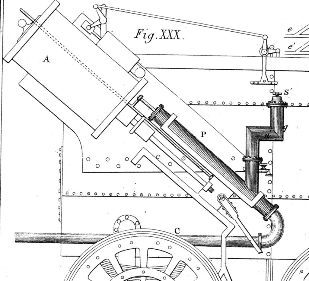
this may help
P, force pump. This draws water via a leather tube, from a barrel placed behind on a train T, and raised to the boiler by tube C.
catfordken
if you cannot see the light at the end of the tunnel,try turning around
|
Country:  United Kingdom ~
Posts: 8294 ~
Member Since: September 28 2006 ~
Last Visit: October 20 2021 United Kingdom ~
Posts: 8294 ~
Member Since: September 28 2006 ~
Last Visit: October 20 2021
|
Alert Moderator
|
|
|
|
Posted - December 19 2015 : 09:13:51 AM
|
I had read that it used a hand pump, but this appears to be tied in with the cross head for a much less labor intensive arrangement. I've seen engines that were decades newer with what is, in principle, the same sort of arrangement, so that practice continued for some time.
Carpe Manana!
|
|
Country: USA ~
Posts: 2418 ~
Member Since: September 17 2013 ~
Last Visit: July 17 2026
|
Alert Moderator
|
|
|
|
Posted - December 20 2015 : 01:52:41 AM
|
Hah! A leather tube! I just knew it couldn't be rubber,
as the first cotton fabric reinforced tube was not
patented until several years after the Rainhill Ordeals
(trials).
Do you have any more of these schematics? I
have had little luck finding anything this good
as yet.
The water feed tube "C" appears to lead into "R,"
assuming that "P" is the pump. The precise
orifice by which cold tender water is injected
would appear about midway up the boiler,
which surprises me, as that would seem to
chill the hot water and presumably reduce
steaming capacity. I wonder if Stephenson
arrived at this critical location so as to not
overly cool the fire box. Any guesses?
Again, fabulous responses to this intriguing
mystery.
On a side note, clearly Stephenson has found
an adequate means of suspending the trailing
axle with leaf springs- which were then known
to be fragile cast iron and better suited for
horse drawn wagons of the age.
Also in my reading, that prior to the Rocket,
Stephenson's talented son, Robert, was on
a three year contract to silver mines in
South America, prior to the Rocket, and
in his absence the elder Stephenson's
iron foundry almost went out of business
because of not having his son's business
acumen present both financially, and
technically.
The reasons for Robert's hiatus to South America
could take another page to analyze. I kind of think
that it was a form of youthful rebellion to show his
Dad, "I can succeed on my own."
So, while George Stephenson's genius cannot
be discounted, much credit has to be given to
his somewhat lesser known son, Robert.
Edited by - Chops124 on December 20 2015 01:58:01 AM
|
|
Country: USA ~
Posts: 11686 ~
Member Since: December 09 2013 ~
Last Visit: May 26 2026
|
Alert Moderator
|
|
|
|
Posted - December 20 2015 : 07:26:27 AM
|
quote:The precise orifice by which cold tender water is injected would appear about idway up the boiler, which surprises me, as that would seem to chill the hot water and presumably reduce steaming capacity. I wonder if Stephenson arrived at this critical location so as to not overly cool the fire box. Any guesses?
Originally posted by Chops124 - December 20 2015 : 01:52:41 AM
|
On most locomotives, the water is injected toward the front of the boiler barrel, as far as you can get from the firebox. This is probably to avoid thermal shock to the hottest and most fragile part of the boiler. An injector heats the water some, but still cools the boiler enough to lower the pressure when water is added. This pump would be putting in water that's just plain cold.
I don't have facts on the matter, but I would guess that, on later Stephenson engines, you'll find the water going in farther away from the firebox. We live and learn.
Carpe Manana!
|
|
Country: USA ~
Posts: 2418 ~
Member Since: September 17 2013 ~
Last Visit: July 17 2026
|
Alert Moderator
|
|
|
|
Posted - December 20 2015 : 10:39:56 PM
|
https://www.youtube.com/watch?v=waNbgqXb1ZE
a repop Rocket
But it do tell how it was revolutionary & how it raced other engines
|
|
Country: USA ~
Posts: 15033 ~
Member Since: February 23 2009 ~
Last Visit: July 19 2026
|
Alert Moderator
|
|
|
|
Posted - December 21 2015 : 02:04:22 AM
|
Blast, the utube video would not open! Still, another
element of understanding has been revealed to me
by scsshaggy.
|
|
Country: USA ~
Posts: 11686 ~
Member Since: December 09 2013 ~
Last Visit: May 26 2026
|
Alert Moderator
|
|
|
|
Posted - December 24 2015 : 11:22:36 AM
|
quote:Blast, the utube video would not open! Still, another
element of understanding has been revealed to me
by scsshaggy.
Originally posted by Chops124 - December 21 2015 : 02:04:22 AM
|
click on the link UNDER the vid
https://www.youtube.com/watch?v=waNbgqXb1ZE
|
|
Country: USA ~
Posts: 15033 ~
Member Since: February 23 2009 ~
Last Visit: July 19 2026
|
Alert Moderator
|
|
|
|
Posted - December 25 2015 : 02:08:33 AM
|
Great vid, Micro. The boiler stays were of particular interest. During
hydrostatic tests, Robert, son of George, noted that a bulge of
boiler end plates of 3/8" on an inch was detected. It is remarkable
to me how close they could measure tolerances. Seeing the
cutaway doubly impressed me with the efficiency of the design.
Edited by - Chops124 on December 25 2015 08:16:28 AM
|
|
Country: USA ~
Posts: 11686 ~
Member Since: December 09 2013 ~
Last Visit: May 26 2026
|
Alert Moderator
|
|