|
|
 Posted - May 08 2012 : 11:35:19 AM Posted - May 08 2012 : 11:35:19 AM


|
Although lately, I seem to have been caught up with "multi-project-concurrent-itis", I have been fairly focused on my Athearn Rotary Snow Plow.
I wanted to power the rotor blade and run a single LED to provide a headlight above the discharge opening, so I have decided to use simple rail electrical pickups from the trucks. I replaced the rubber band wheels and the rear trailing truck wheels with metal ones (properly insulated on one side). I came across a fellow's website (Melvine Perry's blogspot), where he did the same thing, using a particular small motor and an LED.
The issue I have is the speed of the rotor. By using a motor, the rotor speed will vary as per current applied, but we are talking about at least 1000 rpm at low current levels, above stall speeds.
How fast should a rotor like this spin and how would I be able to "limit" the current from the rail pickup on its way thru the motor to do so ?
Siouxlake/ Ron
|
Country:  USA ~
Posts: 510 ~
Member Since: September 21 2011 ~
Last Visit: December 21 2014 USA ~
Posts: 510 ~
Member Since: September 21 2011 ~
Last Visit: December 21 2014
|
 Alert Moderator
|
|
|
|
Posted - May 08 2012 : 3:09:22 PM


|
Ron,
A good way to do that, (control speed of the rotor blade) would be to put in a small Potentiometer on the underside of the frame, that has the philips type adjustment screw/knob, to adjust the voltage going to the motor from one of the trucks....
One that looks like this:
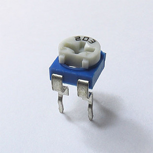
Then you can take a screw driver to adjust how much voltage is going to the motor, which will determine how fast the blades will spin!
Actually a BETTER location for this, would be under the smoke box cover on the rear of the rotary snow plow, that way you can get to it easier with one, removing tghe shell, OR picking up the item as its on the tracks! Make the smoke box cover remove easier then its factory assembly for this purpose!
HTH
~John
Many have tried to, and failed, ya just can't repair stupid... 
Do NOT try to Idiot-Proof anything!!!! God, will simply create a better......IDIOT!
Edited by - EM-1 on May 08 2012 3:11:25 PM
|
|
Country: USA ~
Posts: 2911 ~
Member Since: March 26 2012 ~
Last Visit: January 14 2014
|
Alert Moderator

|
|
|
|
Posted - May 08 2012 : 3:38:33 PM
|
Good idea John! Not sure of the blade's RPM. These have been made to spin, just never seen one in action or any mentioning of the blade's RPM.
" Heck with counting 'em rivets, TRAINS ARE FOR FUN! Not called the Mad Scientist for nothing either!"
|
|
Country: USA ~
Posts: 3147 ~
Member Since: May 07 2007 ~
Last Visit: June 01 2026
|
Alert Moderator
|
|
|
|
Posted - May 08 2012 : 4:08:08 PM

|
I have some 5k pots I can spare, if you want to try this. I'll have to find them.  I can't imagine the rotor blade would spin more than 1,000 RPM, but then what do I KNOW about rotary snow plows? I can't imagine the rotor blade would spin more than 1,000 RPM, but then what do I KNOW about rotary snow plows? 
Jerry
" When life throws you bananas...it's easy to slip up"
|
|
Country: USA ~
Posts: 3974 ~
Member Since: January 04 2009 ~
Last Visit: January 11 2019
|
Alert Moderator
|
|
|
|
Posted - May 08 2012 : 4:10:16 PM
|
A trimmer or any other pot (aside from heavy duty wire wound ones -- rheostats -- in old powerpacks) will not handle the current draw of a motor. A trimmer pot would likely burn its traces. They are for low current applications within electronic circuits.
The simplest is done with a zener diode and a power resistor, which would get hot.
http://www.reuk.co.uk/Zener-Diode-Voltage-Regulator.htm
A better solution would be a circuit with a regulating transistor.
The Tyco Depot
|
|
Country: USA ~
Posts: 3927 ~
Member Since: June 20 2007 ~
Last Visit: November 19 2015
|
Alert Moderator
|
|
|
|
Posted - May 08 2012 : 4:52:03 PM
|
This is true Nelson, HOWEVER the "Pot" I pictured is for a 12 volt system and that allows something like 100 watts to pass through it without problem!
Remember, 12 VDC, at 250 watts is considered low voltage! Specially under 2 AMPs.
I been using them for years and it works GREAT! You have to be carefull though with pots as they will overheat and burn out the interiors, quicky after you pass 2 AMPs and or 250 Watts.
DCC sound systems have been using them for years and they have ALOT going through them for sound and speed of "blinking" of lights, so.......A low voltage motor, with that inline wouldn't and shouldn't be an issue.
And then with that, you can't control the spin with the Zener diodes or the voltage regular as you can a Potentiometer.
~John
Many have tried to, and failed, ya just can't repair stupid...
Do NOT try to Idiot-Proof anything!!!! God, will simply create a better......IDIOT!
|
|
Country: USA ~
Posts: 2911 ~
Member Since: March 26 2012 ~
Last Visit: January 14 2014
|
Alert Moderator
|
|
|
|
Posted - May 08 2012 : 5:40:52 PM
|
A bit more careful reading of this fellow Perry's article reveals that he hooked up a 180 ohm resistor in series with the motor (from Motorman in TX- located the website easily) and at 12 V, the rotor turned at 150 rpm.
You guys are driving me towards greater complexity, so...if I follow the lead of this modeler's work, the resistor, by limiting current flow to the motor, limits the rotor shaft speed?
Would the addition of a dialable potentiometer then be too much of a limiting element of the circuit, or allow me to adjust the RPMs more discretely, with a small screwdriver, as EM-1 John says? And that item would be located on th underside of the frame to allow for access?
Ron
|
|
Country: USA ~
Posts: 510 ~
Member Since: September 21 2011 ~
Last Visit: December 21 2014
|
Alert Moderator
|
|
|
|
Posted - May 08 2012 : 5:55:44 PM
|
Ron,
The Potentiometer would allow better RPM control of the blade spin.....You might be able to add the resistor in FRONT of the Potentiometer which would lower the electrick flow to the motor.
As I spoke of the electronics is easy! I've done it ALOT so......
But yes it would allow you to control the spin of the blades more closely to your liking, wether fast or slow......
You could put the Potentiometer one the underside of the frame so you wouldn't have remove the shell to make adjustments.....I myself, had added them under the boiler front of the snow blower on the Athearn unit. As this is a GREAT location......as long as the boiler front is easily removable.....
~John
Many have tried to, and failed, ya just can't repair stupid...
Do NOT try to Idiot-Proof anything!!!! God, will simply create a better......IDIOT!
|
|
Country: USA ~
Posts: 2911 ~
Member Since: March 26 2012 ~
Last Visit: January 14 2014
|
Alert Moderator
|
|
|
|
Posted - May 08 2012 : 7:02:31 PM
|
| If you don't have a Phillips use a flathead screwdriver small enough to fit the head hehe
|
|
Country: USA ~
Posts: 15027 ~
Member Since: February 23 2009 ~
Last Visit: June 02 2026
|
Alert Moderator
|
|
|
|
Posted - May 08 2012 : 10:33:50 PM
|
quote:
DCC sound systems have been using them for years and they have ALOT going through them for sound and speed of "blinking" of lights, so...
Originally posted by EM-1 - May 08 2012 : 4:52:03 PM
|
John, the trimmers in DCC circuits are subject to a very small amount of current because of where they are in the circuit, by design. They control a power chip or transistor that varies the volume of the sound system, or a the output of regulated power supply, for e.g. I'd like to know the rating on that trimmer, but that's why old powerpacks had heavy duty rheostats.
Even the pots in my good speakers for adjusting the mids and tweeters are wire wound because of the wattage they can handle.
Edit: I think you must be confusing resistance and current. Most trimmers are rated at 1/4 watt. Here is a variable resistor rated at 100. It's a rheostat.
/tyco/forum/uploaded/NickelPlate759/ceramic-disk-variable-resistor-rheostat-100-watt-ohm-150193c.jpg
http://www.sourcingmap.com/ceramic-disk-variable-resistor-rheostat-100-watt-ohm-p-150193.html
The Tyco Depot
Edited by - NickelPlate759 on May 08 2012 10:47:54 PM
|
|
Country: USA ~
Posts: 3927 ~
Member Since: June 20 2007 ~
Last Visit: November 19 2015
|
Alert Moderator
|
|
|
|
Posted - May 09 2012 : 07:59:15 AM
|
Nelson,
Yes thats a Reostat, thats whats in power packs to control voltage directly from the supply.
NOW the AMPs and the Wattage here is high, its comming direct, once you run it through the rails (eats up AMPs) and then to lights and whatever else your dropping the over all voltage, if that POT is used in line with a small motor, to limit the voltage, it be OK to handle what little is comming into the snowplow frame!
NOW, if the case may be, the small POT won't handle the lowering voltage at the same location of the Reostat, as the AMPs and Wattage is high....
You would be stepping it down to work, and as said, if it does look to create an issues, you can always add in a resistor before the POT.
Remember your not "stopping" the flow, or AMPs, your merely slowing them down which controls the speed the blades would spin! a voltage regular in this location would work too, but you would have no control over how fast the blades spin!
NOW another twist would be to get a 6 volt DC regulator, and a 6 volt motor, and run the POT after the regular, and before the motor and you would be able to step it down like that as well!
One thing forsure on any of these, it be a constant voltage supply, it would be constant lighting the motor wouldn't slow daown and speed up as the voltage lowered and went high at times, it be steady!
~John
Many have tried to, and failed, ya just can't repair stupid...
Do NOT try to Idiot-Proof anything!!!! God, will simply create a better......IDIOT!
|
|
Country: USA ~
Posts: 2911 ~
Member Since: March 26 2012 ~
Last Visit: January 14 2014
|
Alert Moderator
|
|