|
|
 Posted - June 10 2019 : 8:45:23 PM Posted - June 10 2019 : 8:45:23 PM


|
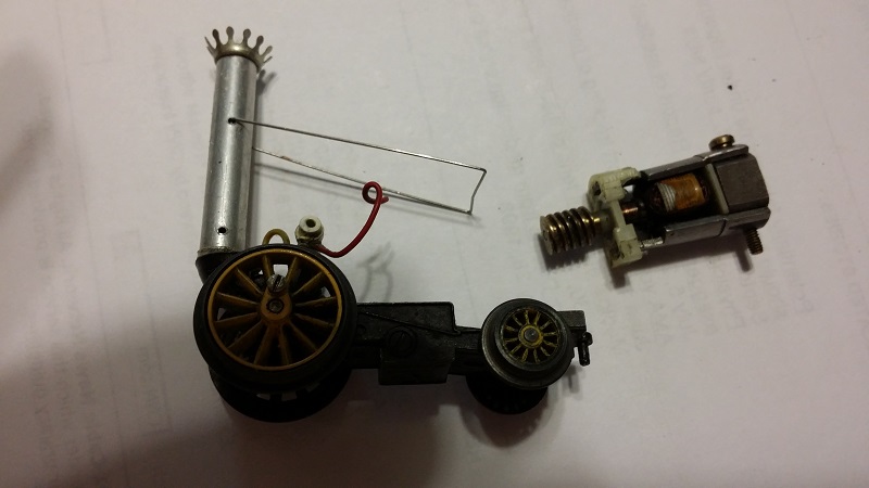
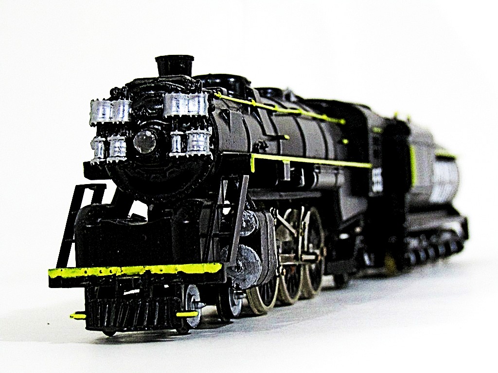
Trying to get this old gem working again. I am baffled by a number of things:
1. where is the positive and ground points on the motor?
2. Assuming the loose red wire is a broken off positive lead, where did it go to?
3. The little white suppressor thing, is that necessary? Can it be removed or should I
leave it alone?
4. Is there a suitable replacement motor, and if so, how does one swap out the worm? Would I
need a miniature gear puller?
|
Country:  USA ~
Posts: 11193 ~
Member Since: December 09 2013 ~
Last Visit: April 19 2024 USA ~
Posts: 11193 ~
Member Since: December 09 2013 ~
Last Visit: April 19 2024
|
 Alert Moderator
|
|
|
|
Posted - June 11 2019 : 06:22:22 AM
|
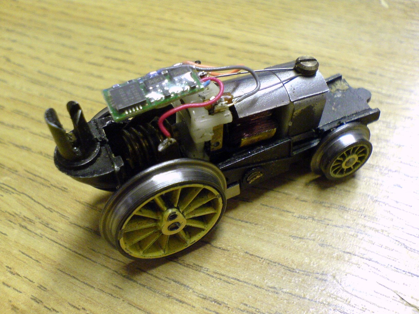
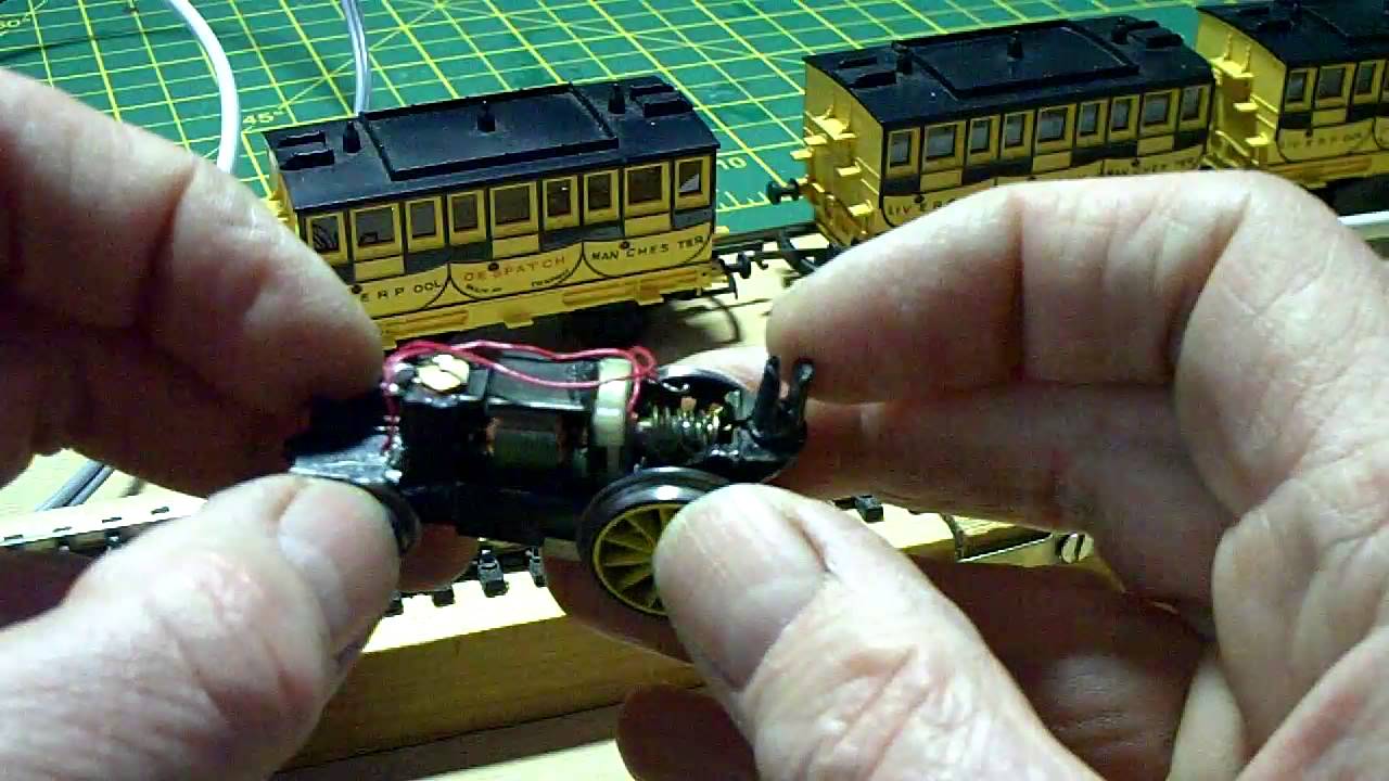
As I'm by no means an electrical expert...here are photos I found on Google that do a good job of showing where the wires connect (the first one is illustrating how someone DCC'd a Rocket.)
Hope this helps...somewhat..
"Let your light so shine before men, that they may see your good works, and glorify your Father which is in Heaven." - Matthew 5:16
Youtube Channel: www.youtube.com/rpmodelrailroads
Instagram: https://www.instagram.com/rp_model_railroads/
|
|
Country: USA ~
Posts: 4669 ~
Member Since: August 11 2017 ~
Last Visit: July 20 2023
|
Alert Moderator

|
|
|
|
Posted - June 11 2019 : 11:01:36 AM
|
These are sweet little beasts, made in the early 1960s and then again around 1979/80, but never since. Sadly they are little tempremental, as I am sure you already know.
The X500 Motor is bespoke to this model, it was similar to the later Minic Motorways Jet Speed motors, but had a longer shaft and was wound differently. I bought a spare motor direct from Hornnby in the early 80s as my model had also failed. They have not been available for some time and I have never known anyone to be able to commercially re-wind these
The model has a split chassis, which was an early use of this type. So essentially you need a connection from each side of the chassis going to the brushes, which seem to be missing, along with the brush spring, brush spring insulation and connecting rods.
Here is the service sheet for the motor: http://www.hornbyguide.com/service_sheet_details.asp?sheetid=253 <http://www.hornbyguide.com/service_sheet_details.asp?sheetid=253>
And here is the one for the complete Loco - http://www.hornbyguide.com/service_sheet_details.asp?sheetid=252 <http://www.hornbyguide.com/service_sheet_details.asp?sheetid=252>
Here is a later service sheet for the loco, which I think is a little clearer: http://www.hornbyguide.com/service_sheet_details.asp?sheetid=127 <http://www.hornbyguide.com/service_sheet_details.asp?sheetid=127>
You will note that the early service sheet shows a Suethe type smoke unit in the chimney whilst the later one now shows some hind of supressor..
To specifically answer your question - The motor is held into the bigger half the metal frame by the long screw that is still present. The scew head end is also the anchoring point for the kind of V shaped brush spring. One side of the spring is insulated with some sleeving and the red wire goes to a tag that clips in here with the brush. On the other side the bare metal of the spring touches the brush directly and makes the second electrical connection.
Whizzzzzz! Off you go, or quite possibly not, given how awkward these things can be, but sdaly that is all the help I can offer.
James
|
Country:  United Kingdom ~
Posts: 128 ~
Member Since: December 10 2016 ~
Last Visit: December 04 2020 United Kingdom ~
Posts: 128 ~
Member Since: December 10 2016 ~
Last Visit: December 04 2020
|
Alert Moderator
|
|
|
|
Posted - June 11 2019 : 12:42:47 PM
|
Thank you for that, it is not split down the center, but
does seem to be split down one side with a thin layer
of plastic, or something, separating the two halves.
What I see in your image might appear to be
an N scale decoder, not sure at all, really, as it
has only two, not four wires.
None the less, all the bits that were last in it when
it ran are there. The only thing is the red wire is
disconnected, and maybe that is the root of the
entire problem...
Thank you for the diagrams, which I just looked at,
and the brush assembly appears to have vanished.
This may end up being a display piece, after all.
I do know a bloke locally who is pretty clever
with small electric train motors, I'll have him take
a look at it.
Edited by - Chops124 on June 11 2019 12:45:43 PM
|
|
Country: USA ~
Posts: 11193 ~
Member Since: December 09 2013 ~
Last Visit: April 19 2024
|
Alert Moderator
|
|